
Atmospheric rotisserie burner with convection heating

Active Publication Date: 2017-03-23
7794754 CANADA
View PDF17 Cites 64 Cited by
  • Summary
  • Abstract
  • Description
  • Claims
  • Application Information

AI Technical Summary

Benefits of technology

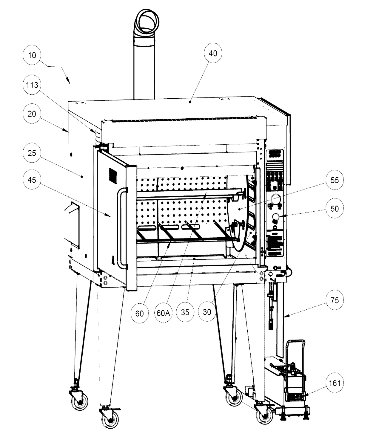
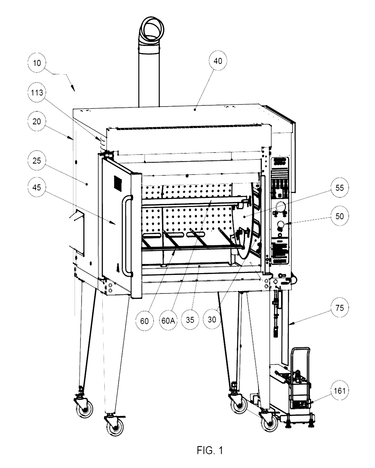
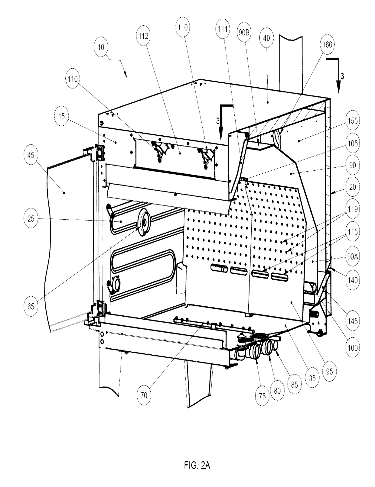
The present invention provides a rotisserie oven that combines the benefits of flame heating and convection heating to cook aesthetically- and gastronomically-pleasing food. The invention includes a webbing between the flame and convection fans to block the full force of air from destabilizing the flame while allowing the flame to remain visible. The invention also provides a method for cooking food simultaneously using both flame and convection heating to achieve simultaneous efficiency and aesthetics. The invention also includes a substrate for supporting a food item, a first plenum, a second plenum, a flame heating element, and at least one air movement device to improve cooking evenness and efficiency.

Problems solved by technology

However, loading multiple food items, such as chickens, on each spit is time and labor intensive.
However, because the electric heating elements are susceptible to burnout when exposed to grease and oil from the food, they are typically placed near or on the ceiling of the rotisserie.
Suboptimal placement of heating elements and fans produce uneven temperatures throughout the cavity.
These burners are extremely susceptible to moisture and clogging and not ideally suited for auto-wash systems.
While flame heating is desirable both aesthetically and taste-wise, the fans used to circulate air in forced convention rotisseries will extinguish flame heating elements, or else divert the flames away from the flame sensor, thereby causing a false loss of ignition signal.
When the flame becomes extinguished, the temperature in the cooking cavity can quickly decrease, which increases the cooking time.

Method used


Image

  • Atmospheric rotisserie burner with convection heating
  • Atmospheric rotisserie burner with convection heating
  • Atmospheric rotisserie burner with convection heating

Examples


Embodiment Construction

[0028]The foregoing summary, as well as the following detailed description of certain embodiments of the present invention, will be better understood when read in conjunction with the appended drawings.

[0029]As used herein, an element step recited in the singular and preceded with the word “a” or “an” should be understood as not excluding plural said elements or steps, unless such exclusion is explicitly stated. Furthermore, the references to “one embodiment” of the present invention are not intended to be interpreted as excluding the existence of additional embodiments that also incorporate the recited features. Moreover, unless explicitly stated to the contrary, embodiments “comprising” or “having” an element or a plurality of elements having a particular property may include additional such elements not having that property.

[0030]The present invention is directed to a cooking apparatus, such as a rotisserie oven, having a flame heating element and fans so as to cook food using co...


PUM


Abstract

The present invention provides a device for cooking food that has a cooking cavity defined by a front wall, a back wall that opposes the front wall, two opposing side walls, a ceiling, and a floor that opposes the ceiling; a substrate for supporting a food item, the substrate substantially enclosed by the cavity; a first plenum spanning between the two opposing side walls, said plenum comprising a first segment proximal to the back wall, a second segment proximal to the ceiling, and at least one third segment that joins the first segment and the second segment; a second plenum positioned proximal to but medially displaced from the first plenum; a flame heating element located between the first plenum and the second plenum; and at least one air movement device located proximal to a region in which the front wall and ceiling intersect.

Description

BACKGROUND OF THE INVENTION[0001]1. Field of the Invention[0002]This invention is directed to a cooking apparatus that has a flame heating element and convection heating fans.[0003]2. Background of the Invention[0004]Rotisserie ovens traditionally cook food on a multitude of rotating spits contained within the oven's cooking cavity. However, loading multiple food items, such as chickens, on each spit is time and labor intensive. Thus, many rotisserie operators prefer to place the food items in baskets. The baskets, however, maintain their orientation throughout their rotation in the cooking cavity, similar to the way cars on a Ferris wheel maintain their orientation while the Ferris wheel spins. This prevents passengers and food items from falling out of their respective baskets, but it also prevents food in the rotisserie from cooking evenly on all sides.[0005]In order to improve the evenness of cooking, some rotisseries attempt to add an element of convection heating. These rotiss...

Claims


Application Information

Patent Timeline
IPC IPC(8): A47J37/04
CPCA47J37/047A23V2002/00A23L1/0135A47J37/042A23L5/17A47J37/0641
Inventor BUCKLEY, KENNETH MICHAELBANU, CRISTIAN MITROI
Owner 7794754 CANADA
Learn More