

Endocranial endoscope
a technology of endoscope and endoscope body, which is applied in the field of endocranial endoscope, can solve the problems of difficult or impossible to effectively autoclave heat-sensitive components of certain endoscopes or effectively sterilize them using other techniques, and achieve the effect of effectively sterilizing and autoclaving heat-sensitive components
- Summary
- Abstract
- Description
- Claims
- Application Information
AI Technical Summary
Benefits of technology
Problems solved by technology
Method used
Image

Examples
Embodiment Construction
OF PREFERRED EMBODIMENTS
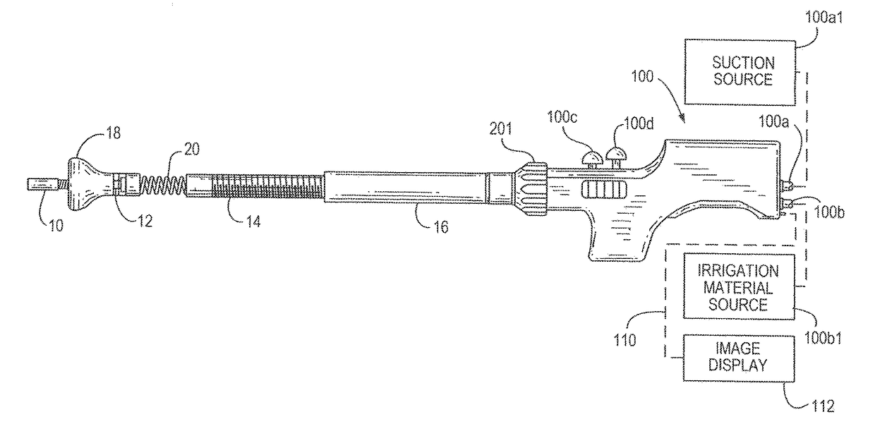
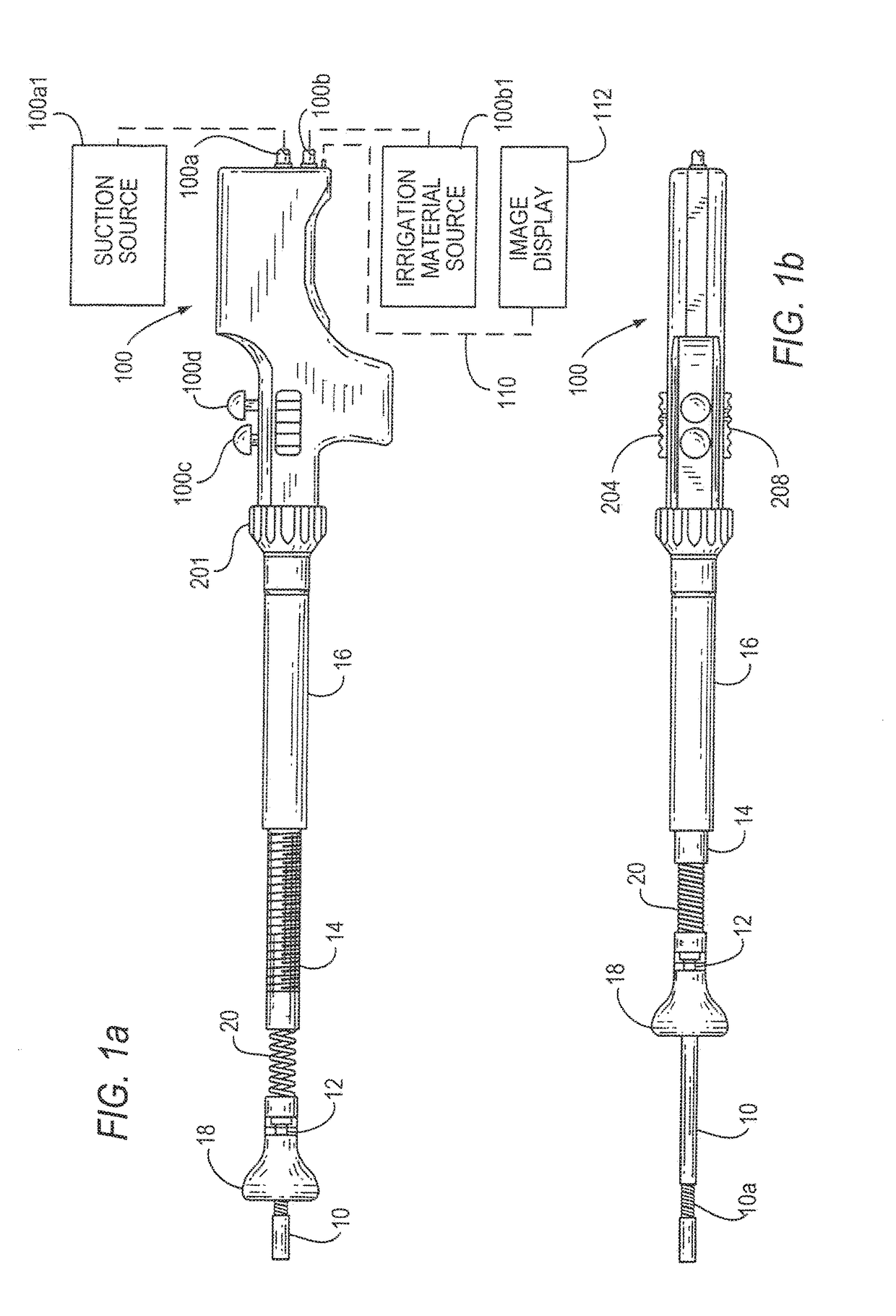
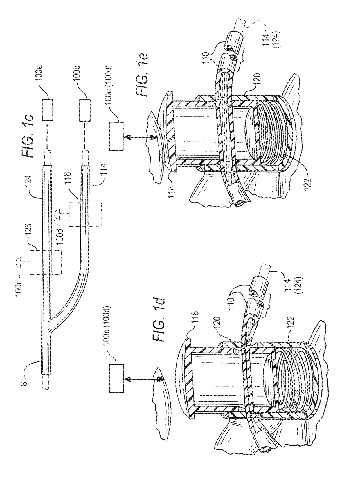
[0020]FIGS. 1a and 1b illustrate one example of an endoscope and FIGS. 2a-2d illustrate distal portions that can be a part of the endoscope of FIGS. 1a and 1b or of alternative endoscope designs. An inner tube 10 protrudes in a distal direction from a sleeve (12) that in turn protrudes distally from an externally threaded middle tube 14. Tube 14 in turn protrudes distally from and threads into an internally threaded, rigid outer tube 16. Inner tube 10 has near its distal end a bending portion 10a that can bend such that the distal end of inner tube 10 points in a direction (and the associated opposite direction) that is within a range of angles from the common axis or parallel axes of sleeve 12 and tubes 14 and 16. A depth indicator ruler 10b (FIG. 2c) extends proximally from a specified distance from the distal tip of tube 10. A stopper 18 slides over sleeve 12 between a distal position (FIG. 2b) to which it is biased by a spring or other biasing element 20 ...
PUM
 Abstract
Description
Claims
Application Information