
Eureka
For R&D, Eureka makes reading and utilizing patents & technical documents easy.
Eureka AIR
Designed for self-driven R&D workflows. Generate viable solutions, solve complex R&D challenges, empower your innovation with AI.

Eureka Materials
Designed for material experts only. Revolutionize your material R&D, from search, analyze, to developing new materials.

TechResearch
Generate reliable direction feasibility study reports for your R&D in just a few steps.

TechSeek
Discover and master advanced knowledge NOW. Basics, ideas, possibilities, all at once.

TechMind
As an expert in R&D Theories, TechMind can generates customized viable solutions instantly.

TechRisk
Analyze your overall solution with one click, know your potential R&D risks in advance.

TechMonitor
Get weekly tech updates, stay abreast of the latest tech innovations and key insights.
Direct resistance heating method and press-molded product manufacturing method
- Summary
- Abstract
- Description
- Claims
- Application Information
AI Technical Summary
Benefits of technology
Problems solved by technology
Method used
Image

Examples
modified example
[0103]According to the embodiments described above, a high-temperature heating region and a non-high-temperature heating region are alternately defined in the longitudinal direction in the heating target region of the plate workpiece. The present invention may be applied also to a plate workpiece described below.
[0104]FIG. 10 is a plan view of a plate workpiece which is different from those illustrated in
[0105]FIGS. 1A, 8, and 9A. The plate workpiece W3 illustrated in FIG. 10 has a shape in which a peak value is present in the variation of the cross-sectional area in the horizontal direction. For example, the thickness is constant and the width monotonously increases in the longitudinal direction and then monotonously decreases. When heating the plate workpiece W3 by direct resistance heating, the first electrode 1 and the second electrode 2 are arranged in a portion having a large width in a heating target region and the electrodes 1 and 2 are connected to current supply equipment ...
examples
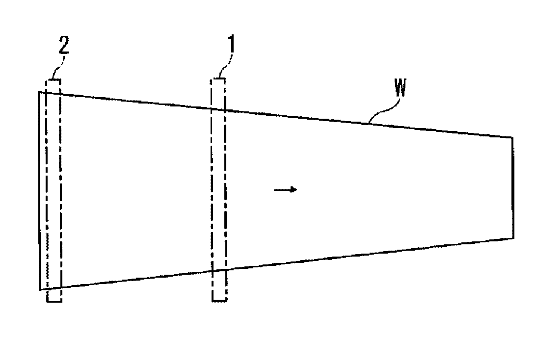
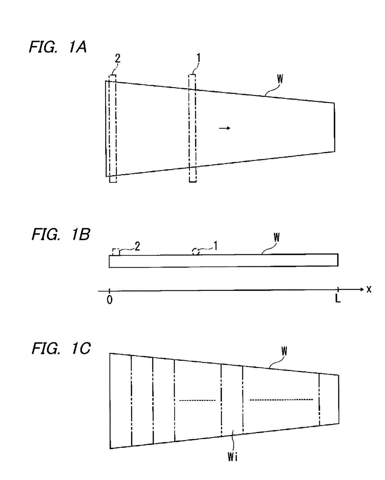
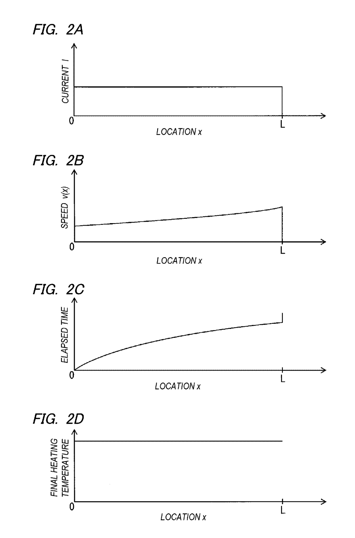
[0109]A plate workpiece having an isosceles trapezoid in a plan view which contains 0.2% of carbon as a material and which has a length L of 500 mm, a thickness of 0.6 mm, a width of 100 mm on one side, and a width of 200 mm on the other side was prepared. A fixed electrode was disposed at one end having a large width and a movable electrode was disposed inside the fixed electrode. An effective current at an AC current of 50 Hz was set to be constant at 2600 A while moving the movable electrode at a speed v(x) satisfying Equation (2). Here, x=0 was set at one end having a small width of the plate workpiece and the large-width side of the plate workpiece was defined as the positive direction of the x axis. The unit was mm. The high-temperature heating region was set to 110≦x≦200, 300≦x≦350, and 450≦x≦500. The time from the heating start to the final heating end was 16.8 seconds.
[0110]The final heating temperature at each position on the x axis was measured using a thermos-camera. The...
PUM
| Property | Measurement | Unit |
|---|---|---|
| Temperature | aaaaa | aaaaa |
| Distribution | aaaaa | aaaaa |
Abstract
Description
Claims
Application Information
 - R&D Engineer
- R&D Manager
- IP Professional
- Industry Leading Data Capabilities
- Powerful AI technology
- Patent DNA Extraction
Browse by: Latest US Patents, China's latest patents, Technical Efficacy Thesaurus, Application Domain, Technology Topic, Popular Technical Reports.
© 2024 PatSnap. All rights reserved.Legal|Privacy policy|Modern Slavery Act Transparency Statement|Sitemap|About US| Contact US: help@patsnap.com