

Light source device
a technology of light source and device body, which is applied in the direction of light source, lighting device details, lighting and heating apparatus, etc., can solve the problems of limiting the dissipation of heat generated and difficulty in reducing the thickness of the device, and achieve the effect of improving the heat radiation property
- Summary
- Abstract
- Description
- Claims
- Application Information
AI Technical Summary
Benefits of technology
Problems solved by technology
Method used
Image

Examples
first embodiment
[0020]First, referring to FIGS. 1 and 2, a light source device according to a first embodiment of the invention will be described.
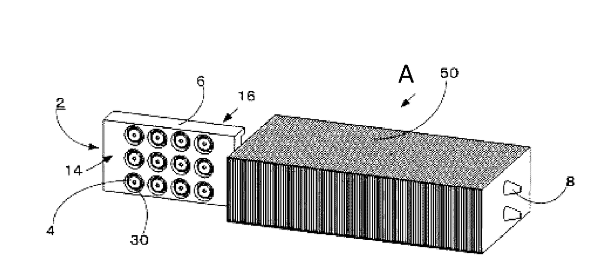
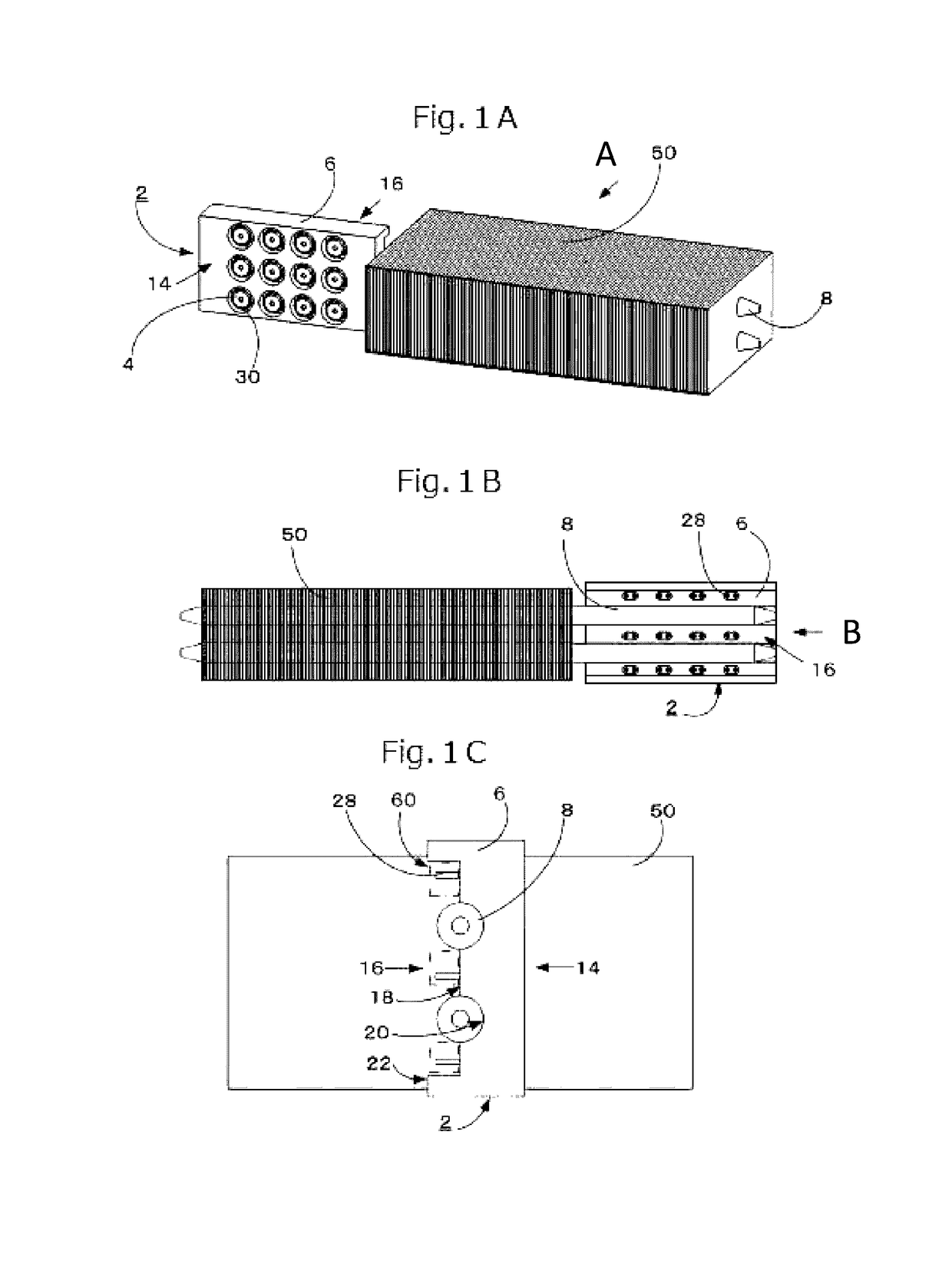
[0021]FIG. 1A is a schematic perspective view of a light source device 2 and a heat radiator 50 thermally connected to the light source device 2 via heat pipes 8, showing a mounting body 6 of the light source device 2, seen from a front surface 14 side which is a light emitting side.
[0022]FIG. 1B is a schematic plan view seen in a direction indicated by the arrow A of FIG. 1A, showing the mounting body 6 of the light source device 2, seen from a rear surface 16 side which is opposite to the front surface. In more detail, FIG. 1B shows the construction such that the heat pipes 8 are attached to the mounting body 6 of the light source device 2.
[0023]FIG. 1C is a schematic plan view of the light source device 2 seen in a direction indicated by the arrow B of FIG. 1B. In more detail, FIG. 1C is a plan view showing the mounting body 6 seen from the end being o...
second embodiment
[0068]Next, referring to FIGS. 3A to 3C and 4A to 4C, a light source device according to a second embodiment of the invention will be described. FIGS. 3A to 3C schematically show the light source device 2 of the second embodiment. In particular, FIG. 3A is a schematic perspective view of the light source device 2 of the second embodiment and the heat radiator 50 thermally connected to the mounting body 6 via heat pipes 8, showing the mounting body 6 of the light source device 2, seen from a front surface 14 side.
[0069]FIG. 3B is a schematic plan view seen in a direction indicated by an arrow D in FIG. 3A, showing the mounting body 6 of the light source device 2, seen from a rear surface 16 side.
[0070]FIG. 3B shows that the heat pipe 8 is attached to the mounting body 6 of the light source device 2. FIG. 3C is a schematic plan view of the light source device 2, seen in a direction indicated by an arrow E in FIG. 3B.
[0071]FIG. 3C is a plan view, seen from the end being opposite to the...
third embodiment
[0083]Next, referring to FIGS. 6A to 6C, a light source device according to a third embodiment of the invention will be described. FIGS. 6A to 6C schematically show a light source device 2 according to a third embodiment of the invention. In particular, FIG. 6A is a schematic perspective view of a light source device 2 and a radiator 50 connected to the light source devices 2 via highly heat conducting elements 12, showing a mounting body 6 of the light source device 2, seen from a front surface 14 side. FIG. 6B is a schematic perspective view of the mounting body 6 of the light source device 2, seen from a rear surface 16 side, in a direction indicated by an arrow H in FIG. 6A, showing that the highly heat conducting element 12 is mounted on the mounting body 6 of the light source device 2. FIG. 6C is a schematic perspective view of the mounting body 6, only showing the mounting body 6 from a rear surface 16 side by removing the highly heat conducting element 12 from FIG. 6B.
[0084]...
PUM
 Abstract
Description
Claims
Application Information