Rotary Machine Diagnostic System

a rotary machine and diagnostic system technology, applied in the direction of dynamo-electric machine testing, short-circuit testing, instruments, etc., can solve the problems of insulation damage to a rotary machine, the rate of operation of the production facility is decreased, and the rotary machine is deteriorated. to achieve the effect of diagnosing a deteriorated condition

Active Publication Date: 2017-03-30
HITACHI LTD
View PDF5 Cites 6 Cited by
  • Summary
  • Abstract
  • Description
  • Claims
  • Application Information

AI Technical Summary

Benefits of technology

[0016]According to the present invention, it is possible to provide a rotary machine diagnostic system that diagnoses a deteriorated condition of a rotary machine by accurately calculating a parameter of a leakage current path equivalent circuit even if a voltage changes transiently.

Problems solved by technology

In a case where an unexpected failure occurs with a rotary machine such as a motor (electric motor) or a generator assembled into a production facility, it is necessary to perform unplanned repair work or unplanned replacement work on the rotary machine such that the rate of operation of the production facility is decreased, or it is necessary to revise a production plan.
However, it is necessary to stop the rotary machine for offline diagnosis, thereby causing a decrease in the rate of operation of the production facility.
For example, one of causes of an unexpected failure is insulation damage to a rotary machine.
However, the method disclosed in NPL 1 has the following problems.
In a case where a signal having a frequency component used to extract a capacitance is small compared to the noise, there occurs a problem that a capacitance extraction error becomes increased.
If the capacitance extraction error is large, in a case where a voltage applied to the rotary machine changes transiently due to change in a load or the like driven by the motor, there occurs a problem that it becomes difficult to accurately calculate a parameter of a leakage current path equivalent circuit.

Method used


Image

  • Rotary Machine Diagnostic System
  • Rotary Machine Diagnostic System
  • Rotary Machine Diagnostic System

Examples


first embodiment

[0028]A rotary machine diagnostic system in a first embodiment of the present invention will be described with reference to FIGS. 1A to 5.

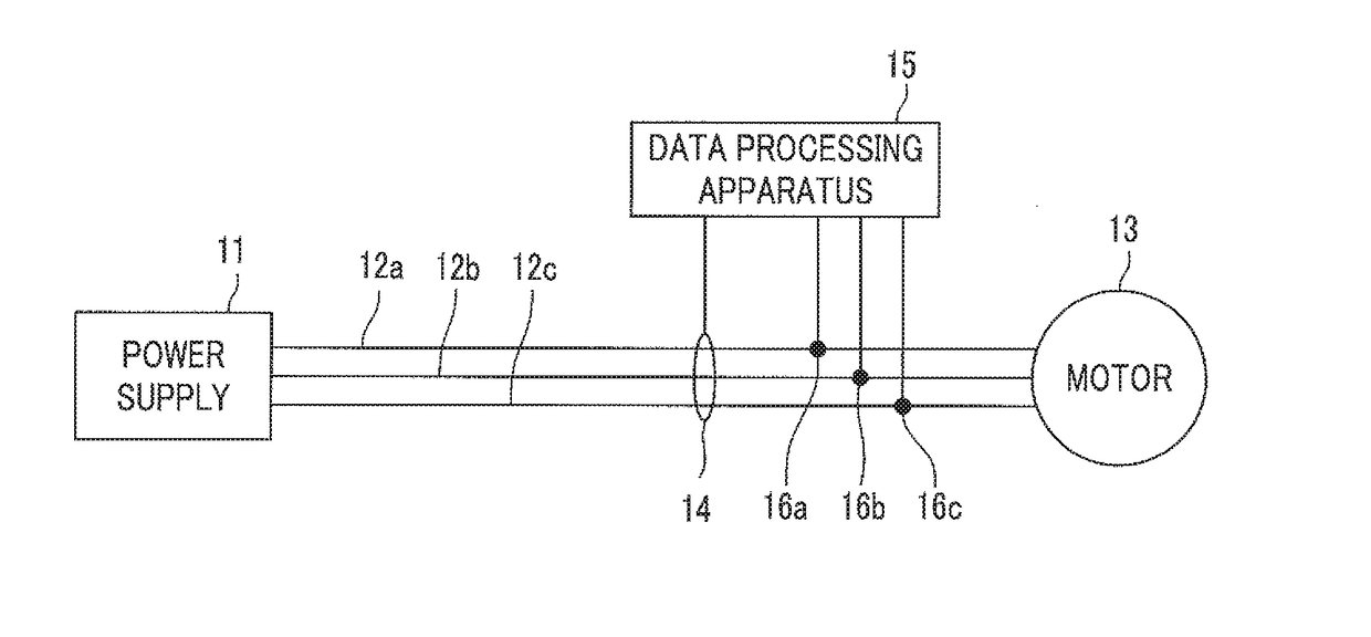
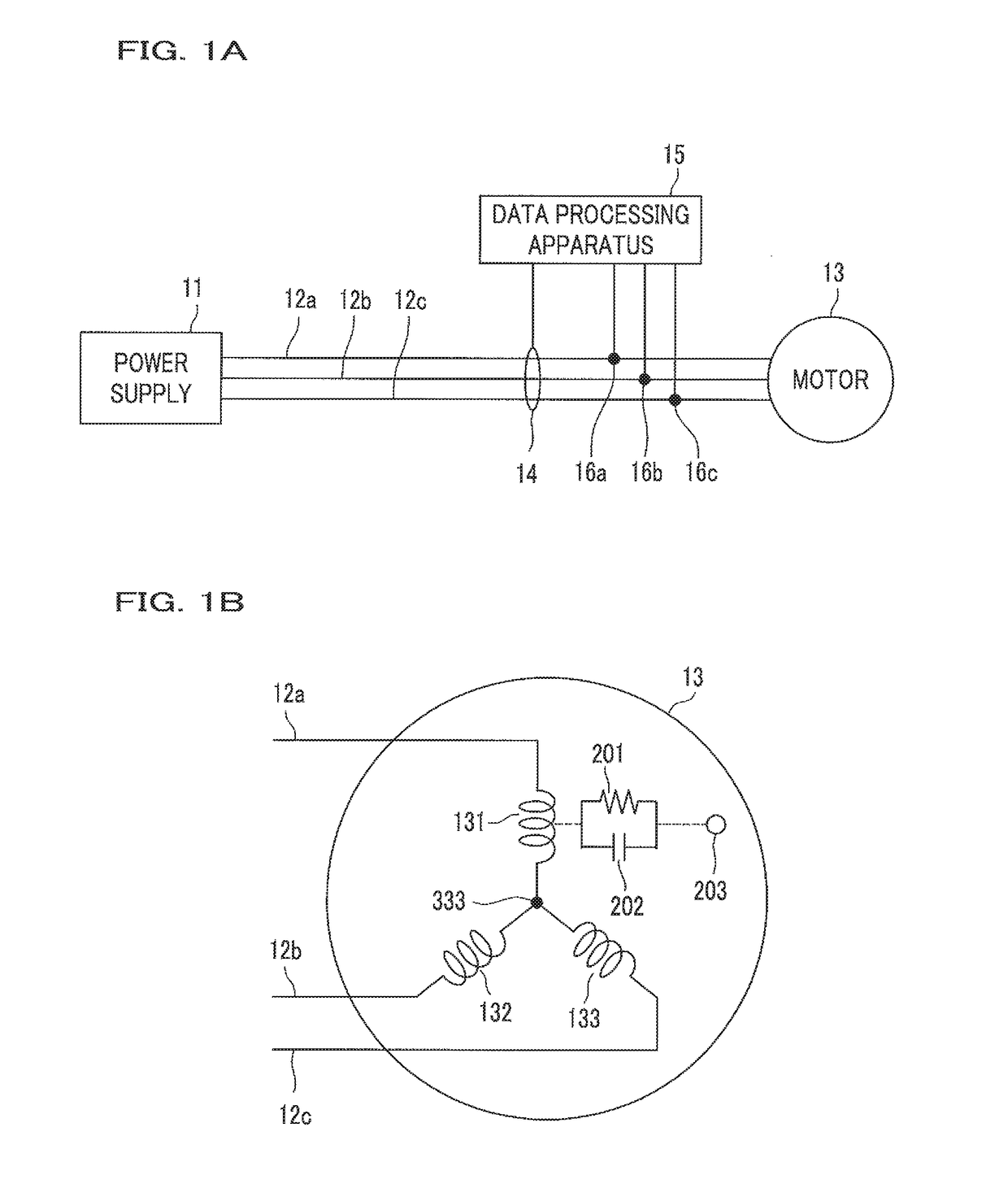
[0029]FIGS. 1A and 1B are diagrams illustrating an example configuration of the rotary machine diagnostic system in the first embodiment of the present invention, in which FIG. 1A illustrates an example of the connection configuration of a rotary machine, and FIG. 1B illustrates a leakage current path of the rotary machine.

[0030]In FIG. 1A, three-phase alternating current power (a U phase, a V phase, and a W phase) is supplied from a power supply 11 to a three-phase motor (electric motor) 13 via power supply lines 12a, 12b, and 12c.

[0031]A current sensor (current measurement means) 14 and voltage sensors (voltage measurement means) 16a, 16b, and 16c are provided on the power supply lines 12a, 12b, and 12c, and respectively measure a zero-phase current and a three-phase phase voltage. Measurement data is input to a data processing apparatus (data ...

second embodiment

[0128]A rotary machine diagnostic system in a second embodiment of the present invention will be described.

[0129]The point of difference between the second embodiment and the first embodiment is a capacitance extraction method.

[0130]In the first embodiment, the capacitance extraction method using Expression 2 is based on a criterion of whether the relationship of i′=i is satisfied; however, comparison may be made based on another criterion of whether a voltage obtained via analysis coincides with a measured voltage. In the second embodiment, a parameter extraction method is performed according to the other criterion.

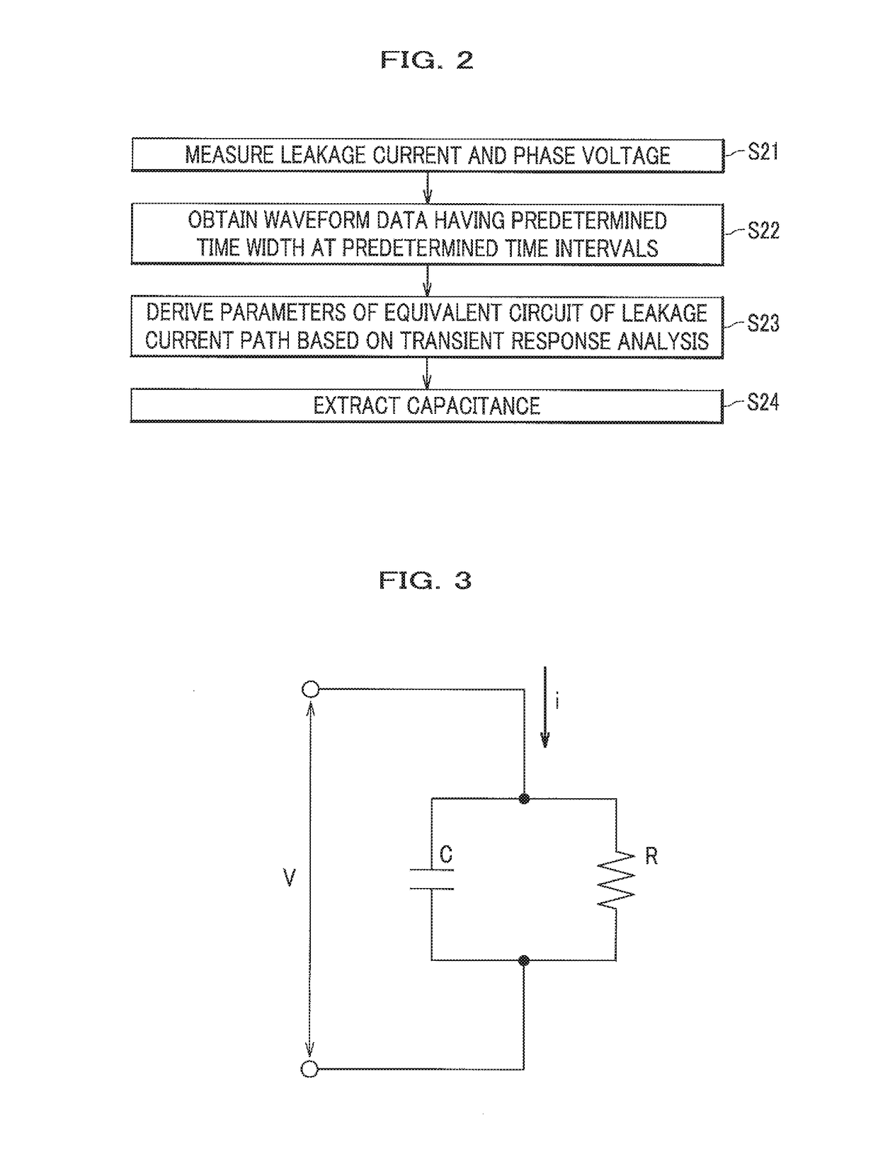
[0131]In a case where i is known in the RC parallel circuit illustrated in FIG. 3, a voltage v′ is represented by Expression 3, and the value of C which satisfies the condition of v′=v may be found from v′ obtained using Expression 3 and a measured voltage v. v(t0) is the value of v at time t0.

v′(t)=v(t0)-(t-t0) / CR+-t / CR∫t0ti(ζ)ζ / CRCζ(Expression3)

[0132]Expression 3 is re...

third embodiment

[0134]A rotary machine diagnostic system in a third embodiment of the present invention will be described.

[0135]The point of difference between the third embodiment and the first and second embodiments is a leakage current measurement method.

[0136]In the first and second embodiments, the current sensor 14 in FIG. 1A is disposed to surround the power supply lines 12a, 12b, and 12c; however, insofar as an increase in leakage current can be measured, a method of connecting a current sensor is not limited to a specific method.

[0137]In a method of connecting a current sensor, a current difference between a coil winding start point and a coil winding end point of each of the power supply lines 12a, 12b, and 12c may be measured. Also, in a method in which a current flowing through each of the power supply lines 12a, 12b, and 12c is measured by a current sensor, and an increased leakage current for a phase is obtained from the sum of the currents, it is possible to obtain the effects of the...


PUM


Abstract

A rotary machine diagnostic system includes: a current measurement unit for measuring a leakage current of a rotary machine; a voltage measurement unit for measuring a voltage of the rotary machine corresponding to the flowing leakage current; and a data processing unit. The data processing unit has a function of performing transient response analysis on a predetermined equivalent circuit model, which is equivalent to a leakage current path of the rotary machine, using current data and voltage data having a predetermined time width which are respectively measured at predetermined time intervals by the current measurement unit and the voltage measurement unit, and a function of extracting parameters of the equivalent circuit of the leakage current path.

Description

CROSS-REFERENCE TO RELATED APPLICATION[0001]This application is based upon and claims priority from the Japanese Patent Application No. 2015-187570, filed on Sep. 25, 2015, the entire contents of which are incorporated herein by reference.BACKGROUND OF THE INVENTION[0002]1. Field of the Invention[0003]The present invention relates to a rotary machine diagnostic system.[0004]2. Description of the Related Art[0005]In a case where an unexpected failure occurs with a rotary machine such as a motor (electric motor) or a generator assembled into a production facility, it is necessary to perform unplanned repair work or unplanned replacement work on the rotary machine such that the rate of operation of the production facility is decreased, or it is necessary to revise a production plan.[0006]A deteriorated state may be ascertained by stopping the motor at a suitable timing and performing a diagnosis for the motor offline so as to forestall an unexpected failure, and as a result, it is poss...

Claims


Application Information

Patent Timeline
Patent Type & Authority Applications(United States)
IPC IPC(8): G01R31/34G06N3/12G01R31/02
CPCG01R31/34G06N3/126G01R31/025G01R31/343G01R31/52
Inventor KATO, TETSUJIMAKI, KOHJINAGATA, MINORI
Owner HITACHI LTD
Why Eureka
Try Eureka