

Vehicle air-conditioning unit
a vehicle air conditioner and air conditioning technology, which is applied to vehicle components, vehicle heating/cooling devices, transportation and packaging, etc., can solve the problems of reducing the dehumidification capacity of the vehicle air conditioning unit, abnormal noise caused by re-evaporation, and the risk of condensed water being applied to the heater cor
- Summary
- Abstract
- Description
- Claims
- Application Information
AI Technical Summary
Benefits of technology
Problems solved by technology
Method used
Image

Examples
first embodiment
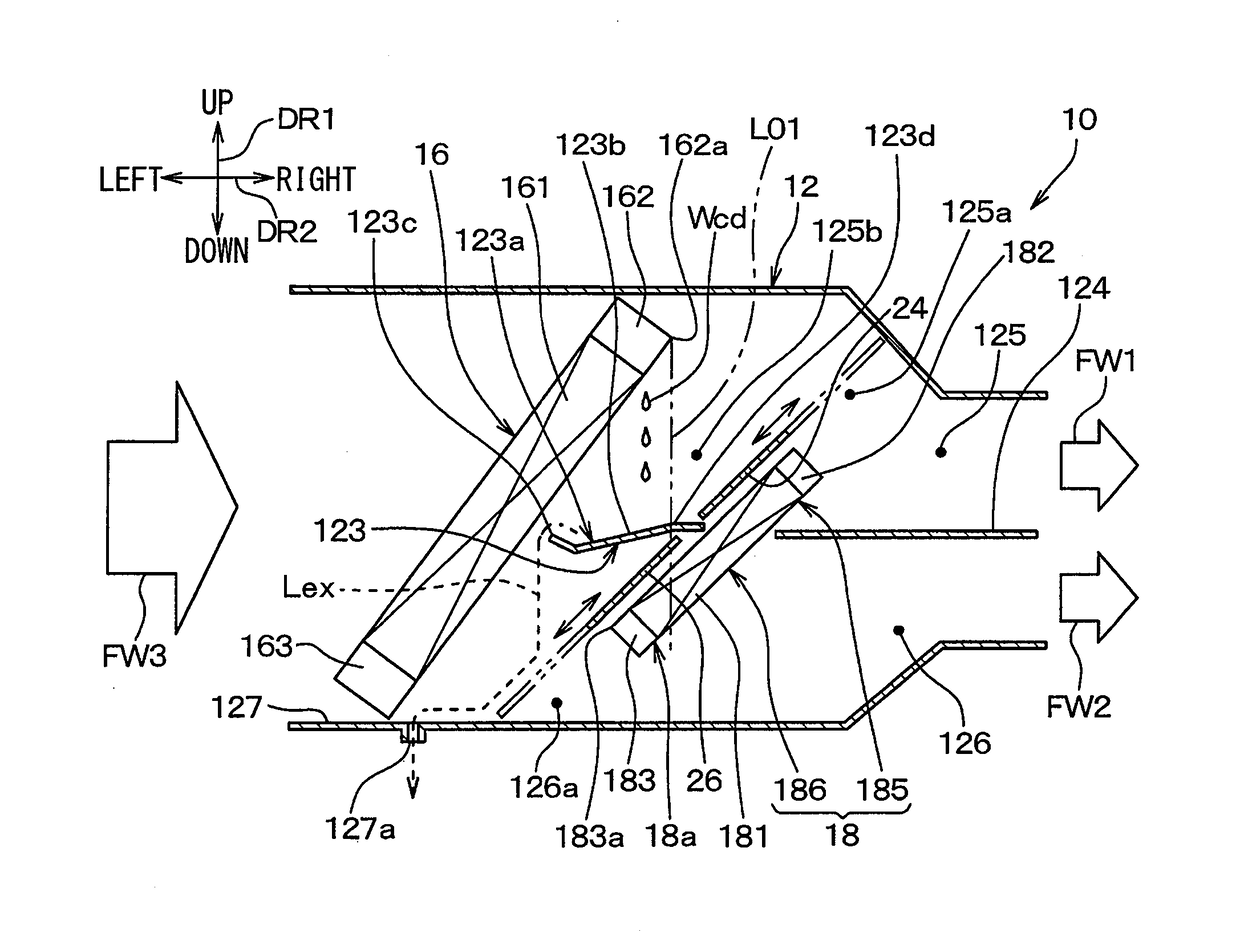
[0020]FIG. 1 is a cross-sectional view illustrating a main configuration of a vehicle air conditioning unit 10 when the vehicle air conditioning unit 10 is viewed from a vehicle longitudinal direction according to the present embodiment. In FIG. 1, upper, lower, right, and left arrows DR1 and DR2 indicate orientations in a vehicle mounted state in which the vehicle air conditioning unit 10 is mounted on a vehicle. In other words, double arrows DR1 in FIG. 1 indicate the vehicle vertical direction DR1, and double arrows DR2 indicate the vehicle width direction DR2. The vehicle vertical direction DR1, the vehicle width direction DR2, and the vehicle longitudinal direction are orthogonal to each other. In the vehicle of the present embodiment, a vehicle right side is provided with a driver's seat, and a vehicle left side is provided with a passenger's seat.
[0021]The vehicle air conditioning unit 10 in FIG. 1 configures a part of the vehicle air conditioning apparatus including a compre...
second embodiment
[0064]Next, a second embodiment of the present disclosure will be described. In the present embodiment, features which are different from those in the above-described first embodiment will be mainly described. Elements which are the same as or equivalent to those in the above-described embodiment will be omitted or simplified in the description. The omission or the simplification is similarly applied to embodiments subsequent to a third embodiment to be described later.
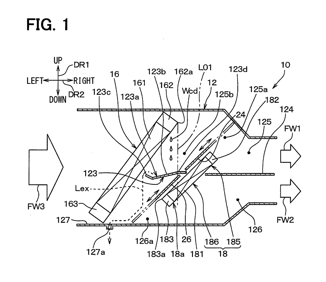
[0065]FIG. 2 is a cross-sectional view illustrating a main configuration of a vehicle air conditioning unit 10 according to the present embodiment, which corresponds to FIG. 1. The vehicle air conditioning unit 10 according to the present embodiment is different from that in the first embodiment described above in that each of air mixing doors 24 and 26 has a rotation type door mechanism.
[0066]As illustrated in FIG. 2, the first air mixing door 24 has the rotation type door mechanism, and opens or closes the upstream ...
third embodiment
[0071]Next, a third embodiment of the present disclosure will be described. In the present embodiment, features which are different from those in the above-described second embodiment will be mainly described.
[0072]FIG. 3 is a cross-sectional view illustrating a main configuration of a vehicle air conditioning unit 10 according to the present embodiment, which corresponds to FIG. 2. The vehicle air conditioning unit 10 according to the present embodiment is different from the second embodiment described above in that a case rib 30 is provided, and a size of a first partition wall 123 is smaller than that of the second embodiment.
[0073]As illustrated in FIG. 3, an air conditioning case 12 includes the case rib 30 as an evaporator support portion for supporting an evaporator 16 on an upper side of the evaporator 16. The case rib 30 is formed integrally to project inward from an outer peripheral wall 121 of the air conditioning case 12. The case rib 30 is provided with a fitting groove...
PUM
 Abstract
Description
Claims
Application Information