Roller gear for a drive system

a technology of roller gears and drive systems, applied in the direction of gearing, hoisting equipment, transportation and packaging, etc., can solve the problem that the components used in roller gears in aircraft landing gears have a finite useful life, and achieve the effect of significant torque-increasing gear ratio

Active Publication Date: 2017-04-06
AIRBUS OPERATIONS LTD
View PDF5 Cites 4 Cited by
  • Summary
  • Abstract
  • Description
  • Claims
  • Application Information

AI Technical Summary

Benefits of technology

[0058]The gear attached to the wheel preferably has a larger diameter than the drive pinion to develop a significant torque magnifying gear ratio. By making use of the large hub diameter in this way, a mass optimised solution can be achieved.

Problems solved by technology

Components used in roller gears in aircraft landing gear have a finite useful life and so roller gears used in this context need dismantling for cleaning and component replacement, particularly for replacing or cleaning and lubricating the rollers and pins on which the rollers are mounted.

Method used


Image

  • Roller gear for a drive system
  • Roller gear for a drive system
  • Roller gear for a drive system

Examples


Embodiment Construction

)

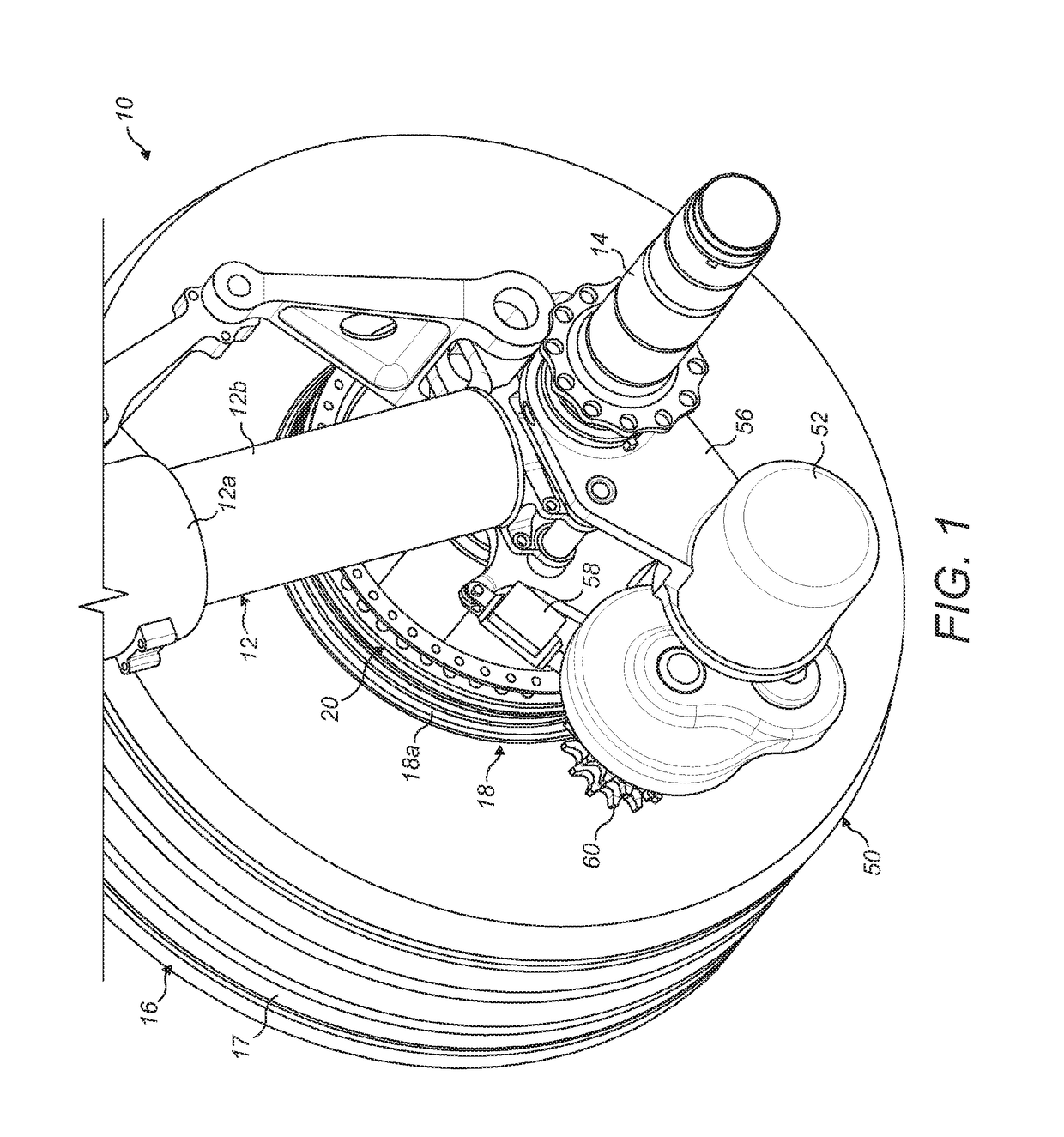
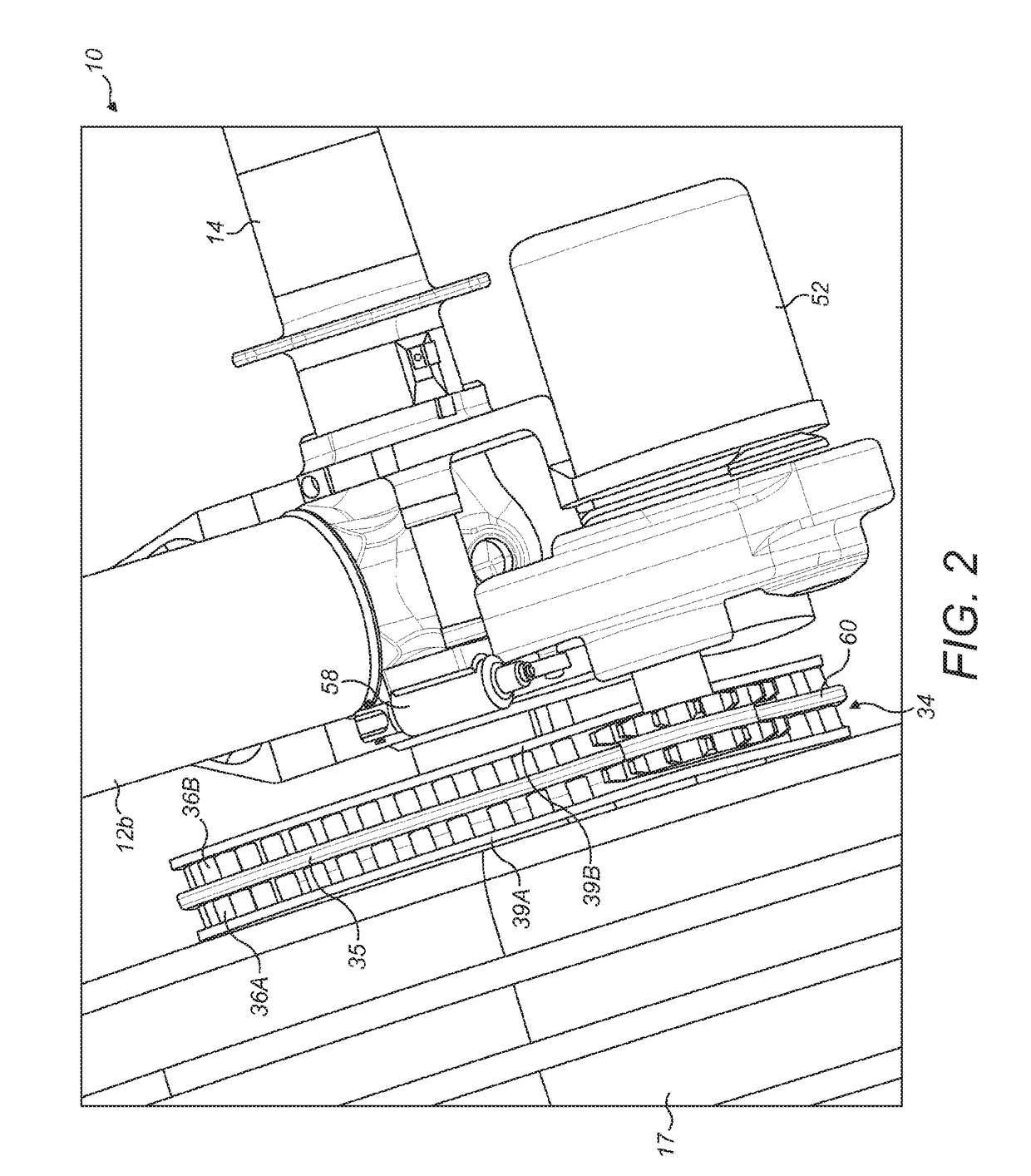
[0076]The illustrated embodiments are shown applied to an aircraft landing gear which has two wheels, but the principles of the embodiments may be applied to landing gear with any number of wheels including only a single wheel. The roller gear of the present invention may be applied in any drive system to engage a corresponding sprocket or pinion. The illustrated embodiment can be applied to a main landing gear (i.e. a landing gear attached to wing structure or fuselage structure in the region of the wings), since the weight supported by the main landing gear is considered to provide the best traction between the wheels and the ground to enable reliable aircraft ground taxiing. However, a drive system incorporating the roller gear of the present invention may alternatively be applied to a nose landing gear (i.e. a steerable landing gear towards the nose of the aircraft). The main landing gear shown is applicable to a single aisle passenger airliner (approximately 150-200 pax), alth...


PUM


Abstract

A roller gear for use in a roller gear and sprocket configuration of a drive system is disclosed, particularly for use in a landing gear drive system of an aircraft. Alternative embodiments and, in particular, means for permitting removal and replacement of rollers and roller mounting pins in the roller gear are disclosed.

Description

FIELD OF THE INVENTION[0001]The present invention relates to a gear for a drive system for rotating one or more wheels of an aircraft landing gear for the purposes of ground taxiing (forwards or reverse) and / or wheel spin-up prior to landing and / or for applying braking torque to the rotating wheel(s).BACKGROUND OF THE INVENTION[0002]Aircraft are required to ground taxi between locations on airfields. An example is taxiing between a runway and the location (e.g. terminal gate) at which the aircraft's passengers are to board or disembark. Typically, such taxiing is achieved by using the thrust from the aircraft's engines to propel the aircraft forwards so that the landing gear wheels are caused to rotate. Since ground taxi speeds are necessarily relatively low, the engines must be run at a very low power. This means that there is a relatively high fuel consumption as a result of the poor propulsion efficiency at this low power. This leads to an increased level of both atmospheric and ...

Claims


Application Information

Patent Timeline
Patent Type & Authority Applications(United States)
IPC IPC(8): B64C25/40F16B5/10F16B21/04F16H55/10
CPCB64C25/405F16B21/04F16B5/10F16H55/10B64C25/34F16C13/00F16H55/17F16B21/02F16H57/0427F16H57/0464F16H57/0471F16H1/00F16H55/00Y02T50/80B64C25/40
Inventor DIDEY, ARNAUDBILLYEALD, RICHARDSETTER, JAMESDICKASON, IAN
Owner AIRBUS OPERATIONS LTD
Why Eureka
Try Eureka