
Busbar

Active Publication Date: 2017-04-06
SAMSUNG SDI CO LTD
View PDF3 Cites 13 Cited by
  • Summary
  • Abstract
  • Description
  • Claims
  • Application Information

AI Technical Summary

Benefits of technology

The patent describes a busbar for connecting cells in a battery module. The busbar has a core and a shell made of a first material, which is an electrically conducting material. The core is made of a second material that has a higher coefficient of thermal expansion than the first material. The shell may have breaking points and is designed to break when the busbar reaches a certain temperature. The second material may be an electrical insulator. The method for manufacturing the busbar involves precooling the core and joining the core and shell together. The technical effect of this invention is to provide an improved busbar that can withstand higher temperatures and maintain electrical conductivity, which increases the safety and efficiency of battery modules.

Problems solved by technology

If the heat emission / discharge / dissipation is not sufficiently performed, a temperature deviation may occur between the respective unit batteries, such that the battery module cannot generate a desired amount of power for motor driving.
In addition, if the internal temperature of the battery increases due to the heat generated from the rechargeable battery, an abnormal reaction occurs therein and thus charging and discharging performance of the rechargeable deteriorates and the life-span of the rechargeable battery is shortened.
In case of failure of the heat dissipater or the cooling device, respectively, or due to another malfunction in one of the battery cells, for example an internal short circuit, thermal runaway of a cell can occur.
It is desirable to reduce, minimize, or eliminate this effect, because overheating and thus failure of the cells can occur, leading to complete failure and possibly the destruction of the battery module.
Hence, heat dissipation continues, possibly affecting other cells of the battery modules or other components of the vehicle or of the device which the battery module is part of.

Method used


Image

  • Busbar
  • Busbar
  • Busbar

Examples


Embodiment Construction

[0025]In the following detailed description, only certain exemplary embodiments of the present invention are shown and described, by way of illustration. As those skilled in the art would recognize, the invention may be embodied in many different forms and should not be construed as being limited to the embodiments set forth herein. Like reference numerals designate like elements throughout the specification.

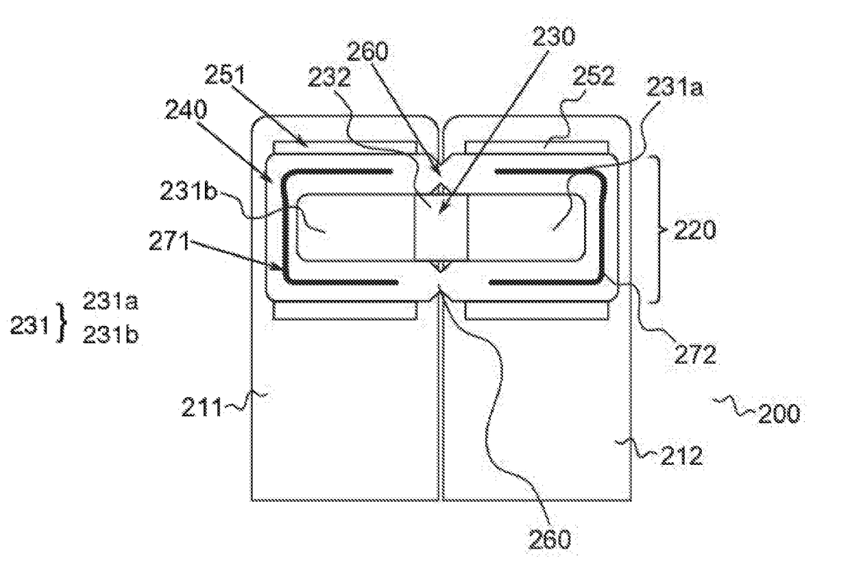
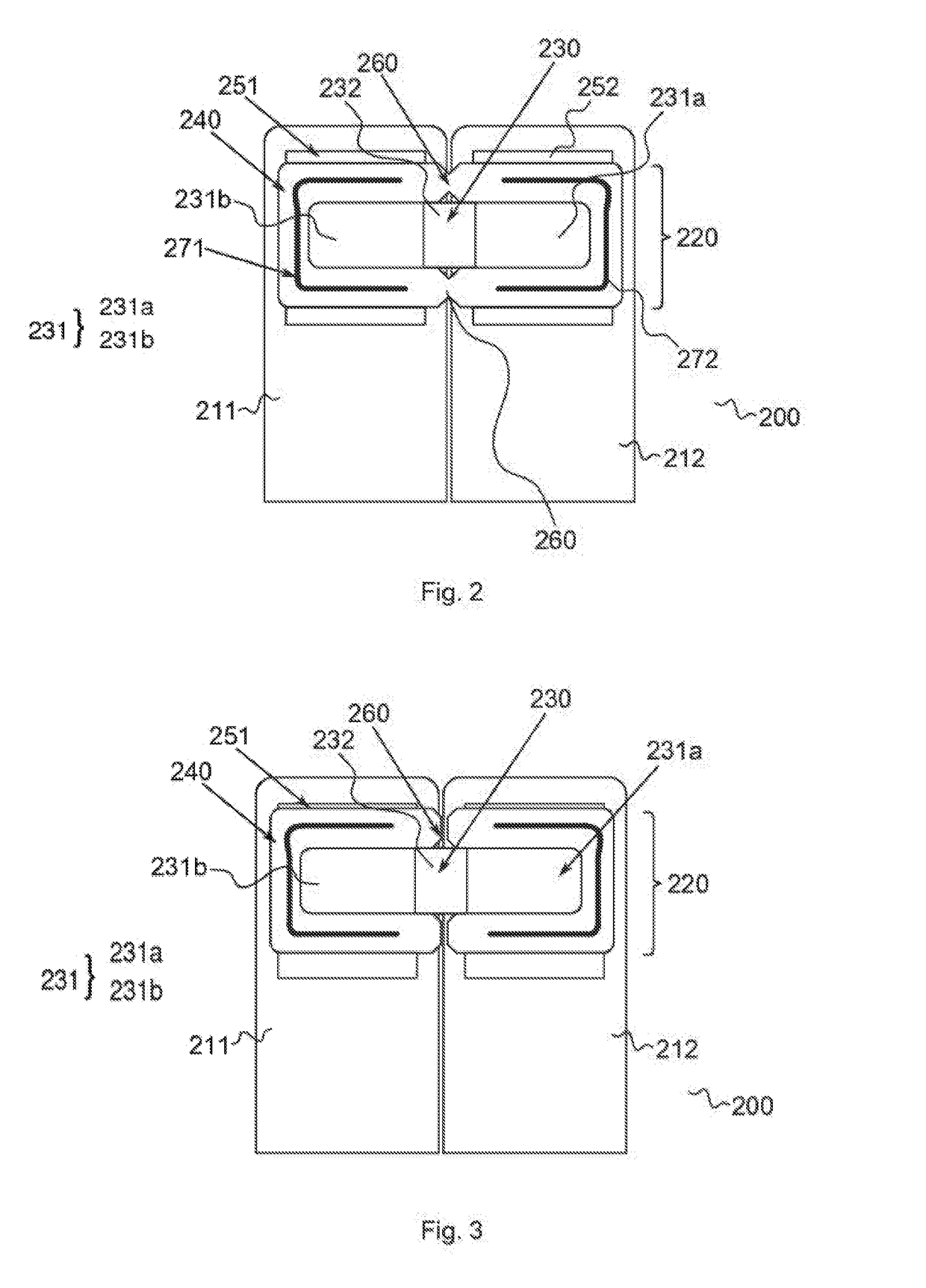
[0026]According to one embodiment of the present invention, a busbar for electrically connecting a plurality of cells of a battery module is provided, including: a core, and a shell at least partially made of a first material, which first material is an electrically conducting material, wherein the core is at least partially made of a second material having a coefficient of thermal expansion which is significantly higher than the coefficient of thermal expansion of the first material. In other words, the busbar is not made of a monolithic piece of solid metal, but has an interna...


PUM


Abstract

The present invention refers to a busbar for electrically connecting a plurality of cells of a battery module. In order to electrically disconnect the battery cells from each other upon thermal runaway of at least one of the cells or short circuit, the busbar includes a core and a shell at least partially made of a first material, said first material being an electrically conducting material, wherein the core is at least partially made of a second material having a coefficient of thermal expansion which is significantly higher than the coefficient of thermal expansion of the first material.

Description

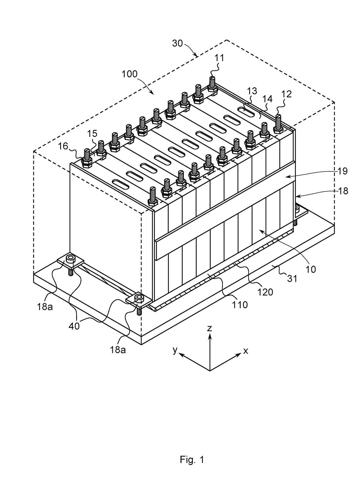
CROSS-REFERENCE TO RELATED APPLICATION[0001]This application claims priority to and the benefit of European Patent Application No. 15188460.8, filed on Oct. 6, 2015, in the European Patent Office, the disclosure of which is incorporated herein by reference in its entirety.BACKGROUND[0002]1. Field[0003]Aspects of the present invention relate to a busbar for electrically connecting a plurality of cells of a battery module. The invention also relates to a battery module including such a busbar as well as to a vehicle including such a battery module and a method for construction of a busbar.[0004]2. Description of the Related Art[0005]A rechargeable battery differs from a primary battery in that it can be repeatedly charged and discharged, while a primary battery makes only an irreversible conversion of chemical energy to electrical energy. Low-capacity rechargeable batteries are used as the power supply for small electronic devices, such as cellular phones, notebook computers and camco...

Claims


Application Information

Patent Timeline
IPC IPC(8): H01M2/34H01M2/20H01M50/209H01M50/244H01M50/264H01M50/502H01M50/505H01M50/516H01M50/522H01M50/526
CPCH01M2/348H01M2200/10H01M2220/20H01M2/206H01M50/581H01M50/505H01M50/264H01M50/502H01M50/522H01M50/244H01M50/516H01M50/526H01M50/209H01R9/00H01M2200/103H01R4/029H01R4/58H01R13/696B60L50/60Y02T10/70Y02E60/10H01M2200/00Y02P70/50H01M50/20
Inventor GOLUBKOV, ANDREJ
Owner SAMSUNG SDI CO LTD
Learn More