Failure isolation method and management server for failure isolation

a failure isolation and management server technology, applied in the field of failure isolation methods and management servers, can solve problems such as difficulty in analyzing the causes of failures of which the rule is not capable, increase in traffic, and various types of failures in the network system, so as to accurately specify the content or position of failures in a network, suppress the consumption of resources

Active Publication Date: 2017-04-06
HITACHI LTD
View PDF7 Cites 6 Cited by
  • Summary
  • Abstract
  • Description
  • Claims
  • Application Information

AI Technical Summary

Benefits of technology

[0023]It is possible to accurately specify the content or position of a failure in a network while suppressing the consumption of resources.

Problems solved by technology

Therefore, there is a case in which an alert (an event indicating a failure) is not obtained or a case in which it is difficult to analyze the causes of a failure of which the rule is not capable of being made.
Various types of failures occur in the network system.
When actions for specifying all of the failures are performed, the amount of traffic increases and a large amount of resources is consumed.
In contrast, when an action is performed only for a limited number of targets, the amount of traffic does not increase, but it is difficult to accurately specify the content or position of a failure.
As a result, when a failure occurs, it is difficult to isolate the failure.

Method used


Image

  • Failure isolation method and management server for failure isolation
  • Failure isolation method and management server for failure isolation
  • Failure isolation method and management server for failure isolation

Examples


embodiment 1

Outline of Process

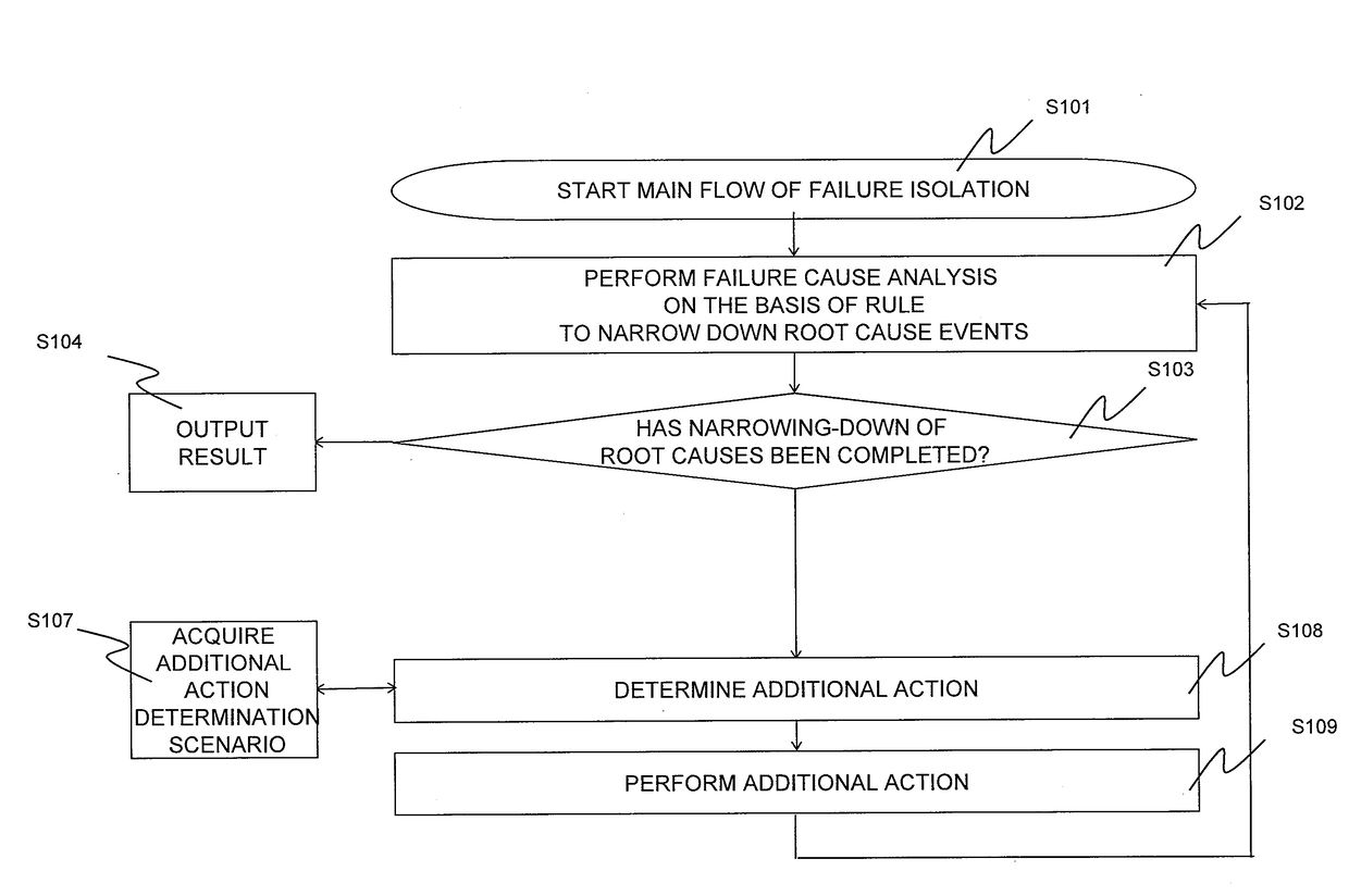
[0071]FIG. 1 is a diagram illustrating the outline of the overall flow of this embodiment.

[0072]First, a failure isolation process starts. This process may be performed in response to an instruction from an operator or may be automatically performed at a predetermined time (S101). A predetermined action is performed to collect an event at the beginning, the event is applied to a rule, and root cause events are narrowed down (S102). As a narrowing-down method, for example, the following methods are used: a method which narrows down the root cause events to only top three candidates with the highest certainty factor; a method which narrows down the events to candidates with a certainty factor of 50% or more; a method which excludes candidates that have a low certainty factor and have a certainty factor difference of 30% or more therebetween from the root causes.

[0073]Then, it is determined whether the narrowing-down of the root causes has been completed (S103). The c...

embodiment 2

[0167]Embodiment 2 of the invention can be applied to a virtual network or a non-virtual network. In addition, each information item illustrated in FIGS. 4 to 11B is corrected to respond to a change in topology. The correction may be manually performed or the information may be automatically updated.

[0168]A response to a dynamic change in topology will be described as Embodiment 2. Embodiment 2 is an example of a method which provides a link connection relationship management table for managing a link connection relationship and automatically updates each information item illustrated in FIGS. 4 to 11B from the link connection relationship management table.

[0169]FIG. 16 is a flowchart illustrating the outline of the entire process of Embodiment 2. The same structures as those in FIG. 1 are denoted by the same reference numerals and the description thereof will not be repeated. Embodiment 2 includes a process which acquires a topology history (S1601). The topology is information indic...

embodiment 3

[0201]In Embodiment 3, an example in which a level learning process is performed on the basis of Examples 1 to 2 will be described. In this embodiment, when the analysis completion determination unit 202 determines that the analysis has been completed, narrowed-down root cause event numbers and the narrowing-down level are stored and the appearance frequency of the level is counted. For the level with a high frequency, the narrowing-down level increases to a high narrowing-down level (a narrowing-down level with a small number) and an additional action is executed.

[0202]FIG. 24 is a table illustrating the comparison between the configuration of a root cause event number-additional action correspondence table 900 according to Embodiment 3 and the configuration of the root cause event number-additional action correspondence table 900 according to Embodiment 1 (FIG. 9). The configuration of the table according to Embodiment 1 is illustrated on the upper side and configuration of the ta...


PUM


Abstract

The failure isolation method includes: a first step of performing a predetermined action for the monitoring target, collecting a failure event which is a result of the action, applying the failure event to a failure cause analysis rule, and narrowing down the root cause events together with certainty factors; a second step of determining whether the root cause event and the certainty factor narrowed down in the first step satisfy a predetermined requirement and whether the narrowing-down has been completed; and a third step of, when it is determined in the second step that the narrowing-down has not been completed, performing a predetermined additional action for the monitoring target, collecting an additional failure event which is a result of the additional action, applying the additional failure event to the failure cause analysis rule, and narrowing down the root cause events together with the certainty factors.

Description

CLAIM OF PRIORITY[0001]The present application claims priority from Japanese patent application JP2015-196596 filed on Oct. 2, 2015, the content of which is hereby incorporated by reference into this application.BACKGROUND OF THE INVENTION[0002]Field of the Invention[0003]The present invention relates to a technique for specifying a failure which occurs in a network system.[0004]Description of the Related Art[0005]When a failure which occurs in a network system is specified, a technique (root cause analysis: RCA) has been known which performs failure cause analysis on the basis of a rule (JP 2012-256355 A).[0006][Patent Document 1] JP 2012-256355 A[0007]When a failure which occurs in a network system is specified, it is necessary to perform an operation for a specific target in the network (this operation is referred to as an “action”), to acquire an event which is generated in response to the action (referred to as “event”), to apply a predetermined rule to the acquired event, and ...

Claims


Application Information

Patent Timeline
Patent Type & Authority Applications(United States)
IPC IPC(8): H04L12/24H04L12/26
CPCH04L41/0631H04L41/0659H04L43/08H04L43/20
Inventor IWAMURA, ATSUSHIYASUDATSUSHIMA, HIDEAKIISHII, HIDEAKIKOMATSUZAWA, ATSUSHI
Owner HITACHI LTD
Why Eureka
Try Eureka