Prosthetic mitral or tricuspid heart valve

a heart valve and prosthesis technology, applied in the field of pathology of heart valves, can solve the problems of poor coaptation of the valve, loss of sealing and effectiveness of the valve, and inability to be very suitable for elderly patients, and achieve the effect of effective anchoring

Active Publication Date: 2017-04-13
VALMY HLDG
View PDF7 Cites 3 Cited by
  • Summary
  • Abstract
  • Description
  • Claims
  • Application Information

AI Technical Summary

Benefits of technology

[0022]The anchoring is thus done by clamp effect done by the different pairs of anchoring spikes, which allows very effective anchoring. The particularity of these spikes is then forming a sort of “crab claw” due to the fact that the points are oriented symmetrically toward one another, making it possible to bite the annular tissue and stabilize the frame of the valve. During the deployment of the prosthesis with the use of the apical approach, the atrial anchoring spikes deploy first, making it possible to catch the annular tissue, then, secondly, over the course of the deployment, the ventricular anchoring spikes deploy in turn and make it possible to perfect the anchoring of the prosthesis, with maintenance of the anchoring spikes in the intra-annular position.
[0023]Thus, the proposed structure allows an implantation that bears on the peri-annular valve tissue first (the anchoring spikes), which is followed by additional bearing on the valve annulus. Indeed, the claw catching system allows catching of the valve tissue and is completed by the intra-annular bearing of the metal structure, in the mitral and tricuspid position as required by the approach used.

Problems solved by technology

A well-known pathology of a heart valve, primarily affecting elderly patients, is the distention of the valve annulus, this distention leading to poor coaptation of the valves and therefore loss of sealing and effectiveness of the valve.
This technique has certain drawbacks, in particular that of not being very suitable for elderly patients.
The existing prostheses of this type are not fully satisfactory, in particular having a risk of bothering, when they are placed, the operation of the aortic valve and risks of migration and therefore obstruction of the ventricular ejection path.
Furthermore, these prostheses are not always very easy to place, and their shape is not perfectly adapted to that of the implantation site.

Method used


Image

  • Prosthetic mitral or tricuspid heart valve
  • Prosthetic mitral or tricuspid heart valve
  • Prosthetic mitral or tricuspid heart valve

Examples


second embodiment

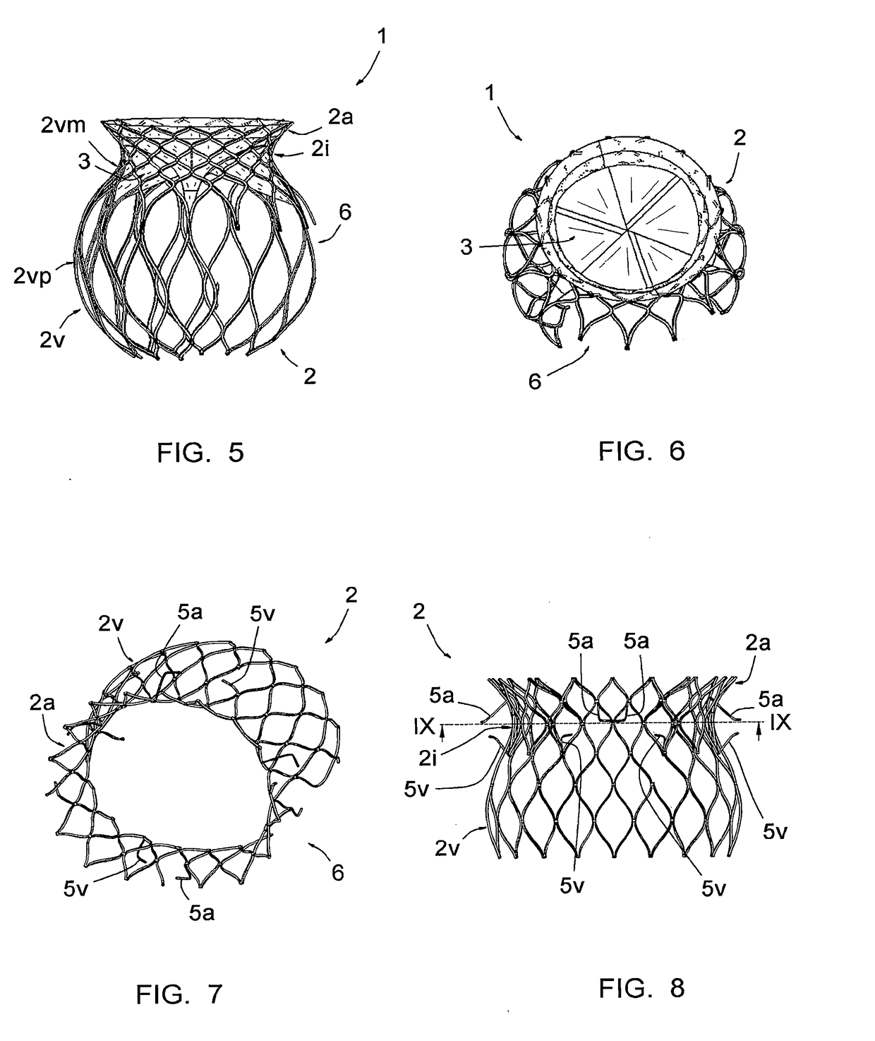
[0069]FIGS. 7 to 9 show, from different angles, the frame 2 of the prosthesis (the prosthetic valve is not shown), intended to treat a mitral valve. For simplification, the parts or elements already described, that are found in this 2nd embodiment, are designated using the same numerical references.

[0070]In this case, the atrial portion 2a is not conical in that it has a cross-section that is not circular, but rather in the shape of a “D with rounded corners and edges” visible in FIG. 9 and shown schematically in FIG. 10. In reference to this FIG. 10, it appears that this section has a rounded posterior portion, a slightly rounded anterior portion and two rounded lateral portions, these different portions being connected to one another by intermediate portions with a smaller curve radius than they themselves have. It will be understood the terms “posterior” and “anterior” above respectively refer to the portion of the prosthesis situated on the posterior side of the mitral valve ann...

first embodiment

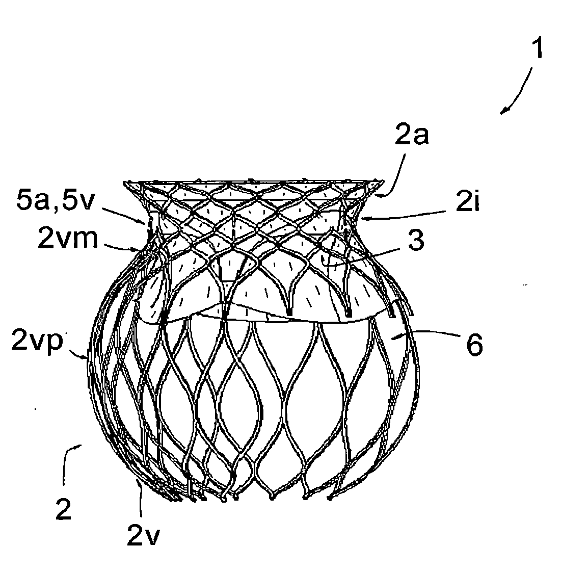
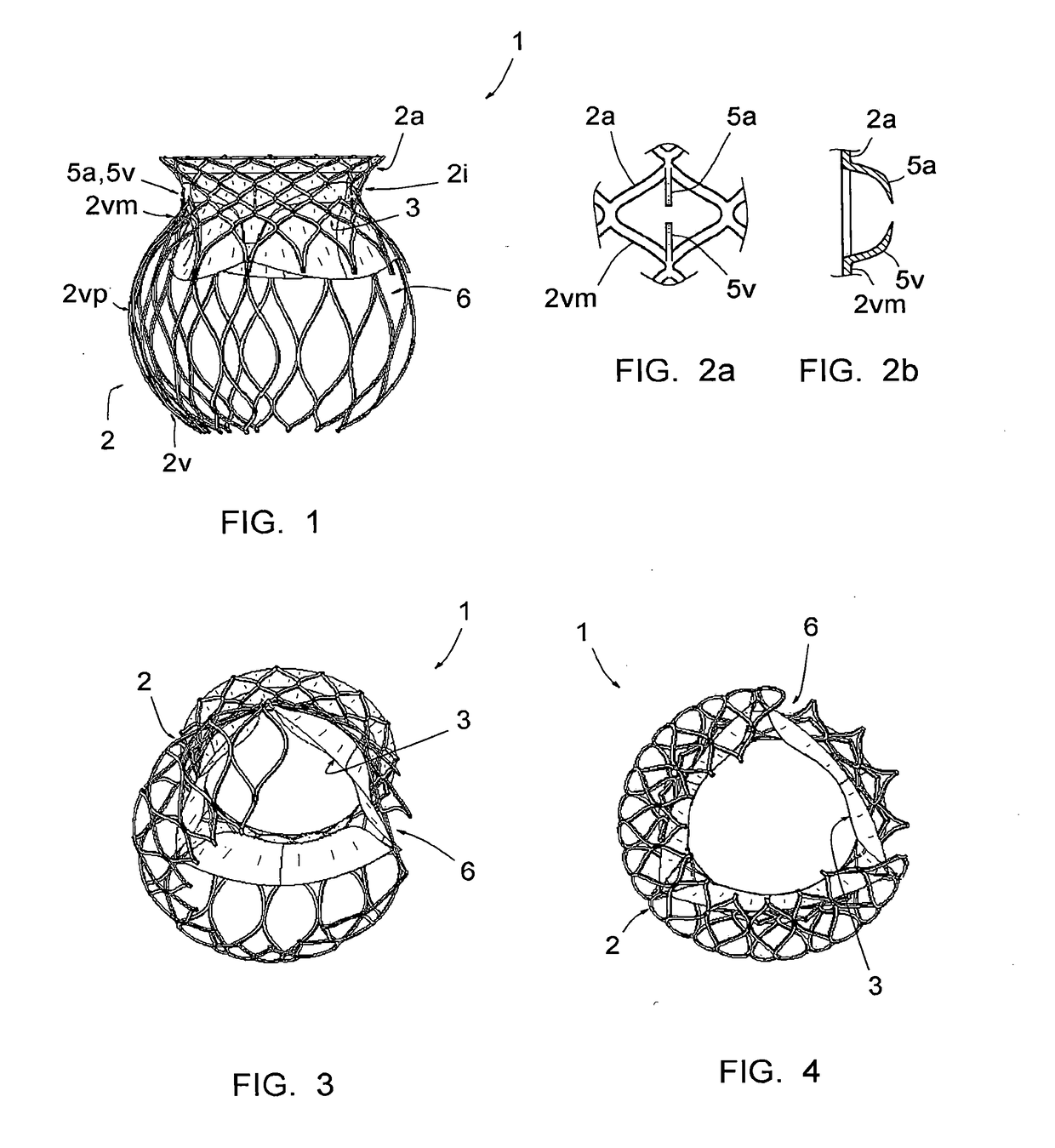
[0071]In the same manner as on the frame the atrial portion 2a flares toward the outside of the prosthesis, having a section increasing from said annular portion 2i toward the end of this atrial portion 2a opposite this annular portion 2i.

[0072]The annular 2i and ventricular 2v portions have shapes similar to those of the prosthesis according to the first embodiment, except that the ventricular portion 2v is closed less at its end opposite the annular portion 2i, being truncated relative to that according to the first embodiment.

[0073]The frame 2 according to the second embodiment differs from those according to the first embodiment by the shape of the anchoring spikes 5a, 5v. Indeed, each anchoring spike 5a, 5v has a base portion connected to the corresponding portion 2a, 2v of the frame 2 and a free end portion that is bent relative to said base portion. This base portion is substantially rectilinear and protrudes from the portion 2a, 2v in a direction forming an angle of about ...


PUM


Abstract

This prosthesis (1), comprises an expandable tubular frame (2) with a mesh structure and a prosthetic valve (3) mounted on this frame;
    • the ventricular portion (2v) of the frame (2) has a large indentation (6) on one side, extending lengthwise from the end of this ventricular portion (2v) that is opposite said annular portion (2i) to the part of this ventricular portion (2v) close to the annular portion (2i), this indentation (6) extending over a sector of the circumference of the prosthesis (1) of about 90 to 140°;
    • said atrial portion (2a) flares toward the outside of the prosthesis, from said annular portion (2i) toward the end of this atrial portion opposite this annular portion, and comprises anchoring spikes (5a) on the side of said annular portion (2i); and
    • said ventricular portion (2v) has a substantially spherical or ovoid shape and comprises anchoring spikes (5v) on the side of said annular portion (2i).

Description

[0001]The present invention relates to a mitral or tricuspid heart valve prosthesis.BACKGROUND OF THE INVENTION[0002]A well-known pathology of a heart valve, primarily affecting elderly patients, is the distention of the valve annulus, this distention leading to poor coaptation of the valves and therefore loss of sealing and effectiveness of the valve.[0003]It is known to treat this pathology by annuloplasty, i.e., by placing a total or partial prosthetic annulus aiming to recalibrate the native valve annulus. This technique has certain drawbacks, in particular that of not being very suitable for elderly patients.[0004]It is also known to implant, above the native valve, a prosthesis comprising an expandable tubular frame and a prosthetic valve mounted on this frame. The tubular frame, frequently called “stent”, has a mesh structure, and comprises an atrial portion, i.e., intended to be placed at the atrium of a heart, a ventricular portion, i.e., intended to be placed at the ventri...

Claims


Application Information

Patent Timeline
Patent Type & Authority Applications(United States)
IPC IPC(8): A61F2/24A61F2/848
CPCA61F2/2418A61F2/848A61F2230/0078A61F2230/0076A61F2002/8483A61F2230/0071A61F2/2412
Inventor MODINE, THOMAS
Owner VALMY HLDG
Why Eureka
Try Eureka