Battery controller

Active Publication Date: 2017-04-13
MITSUBISHI MOTORS CORP
View PDF5 Cites 13 Cited by
  • Summary
  • Abstract
  • Description
  • Claims
  • Application Information

AI Technical Summary

Benefits of technology

[0015]With the configuration [1], when the malfunction of the voltage detector in the battery is detected, the charge current to be supplied to the battery and the discharge current output from the battery are integrated; and when the actual charge current amount obtained by subtracting the integrated value of the discharge current from the integrated value of the charge current is equal to or more than the predetermined value, the charging/discharging to and from the battery is prohibited. Therefore, even after the malfunction of the voltage detector occurs, it is advantageously possible to continuously use the battery while preventing the damage of surrounding members due to influence caused by the overcharge of the battery, for example, due to the malfunction or heat generation of the battery. Further, when the actual charge current amount is in the range less than the predetermined value, the charging of the battery is permitted, and thus it is advantageously possible to prolong the usable period of the battery and improve the convenience of the user, compared to the case where the charging of the battery is prohibited.
[0016]With the configuration [2], when the battery is used as the power supply for driving the electric power vehicle, the electric power vehicle can travel throughout a period of time even after the malfunction of the

Problems solved by technology

The reason is that the battery becomes an overcharge state in a case of exceeding the upper limit state-of-charge of use, the battery becomes an over-discharge state in a case of being below the lower limit state-of-charge of use, and performance of the battery deteriorates even in any case.
In general, a state of charge (SOC) of the battery is calculated based on a voltage value of a battery, but a correct calculation of the SOC becomes difficult when malfunction occurs in a voltage detector that detects a voltage of the battery.
For this reason, when the malfunct

Method used


Image

  • Battery controller
  • Battery controller
  • Battery controller

Examples


Example

[0024]A preferred embodiment of a battery controller according to the invention will be described in detail below with reference to the accompanying drawings.

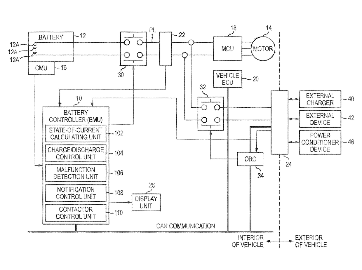
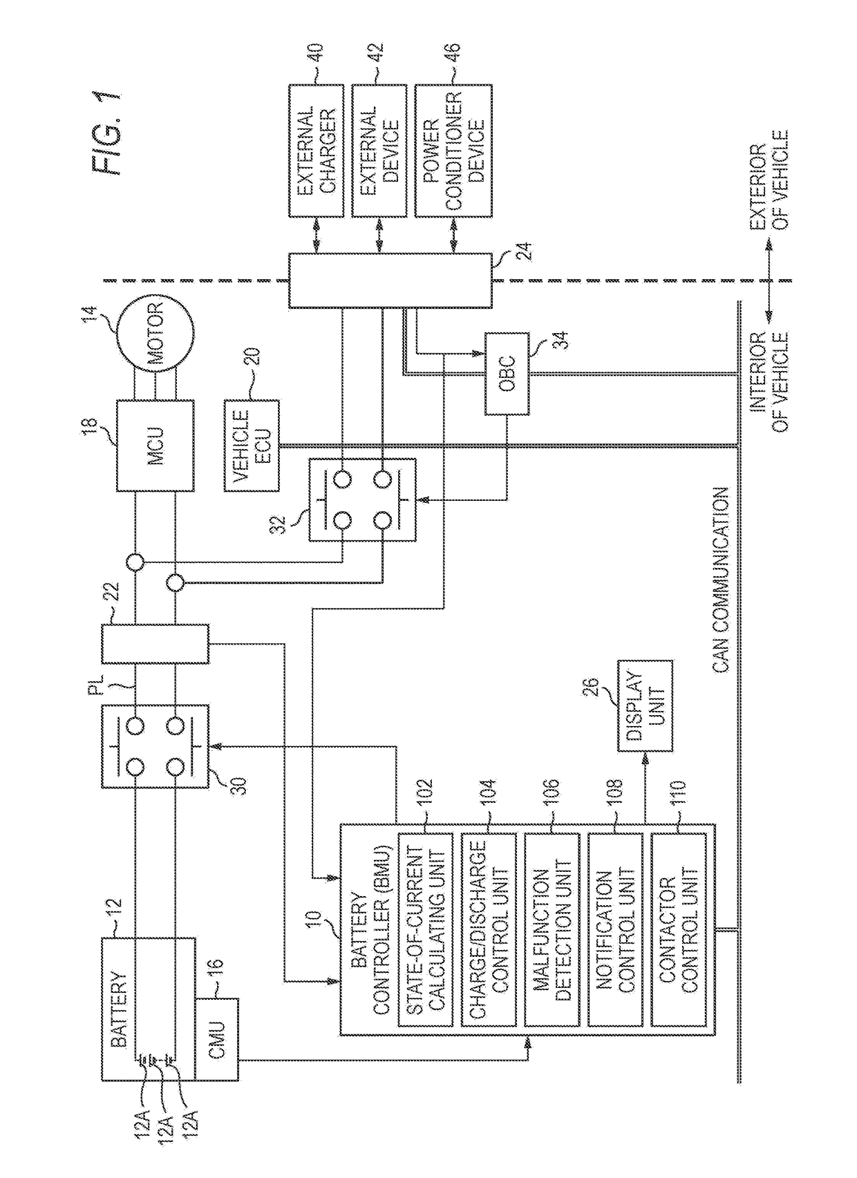
[0025]FIG. 1 is an explanatory diagram illustrating a configuration of a battery controller 10 according to the embodiment.

[0026]The battery controller 10 controls a battery 12 that supplies driving power to a load apparatus. More specifically, the battery controller 10 is a BMU (Battery Management Unit) that monitors a state of charge or the presence / absence of malfunction of the battery 12, for example.

[0027]In the embodiment, the load apparatus is a traveling motor 14 of an electric power vehicle, and the battery 12 supplies driving power to the traveling motor 14. Although a case where only the traveling motor 14 is mounted in a driving source of the electric power vehicle is described in the embodiment, the invention is applicable to a hybrid vehicle mounted with the traveling motor 14 and an engine.

[0028]The embodiment ex...


PUM


Abstract

A battery controller that controls a battery for supplying power to a load apparatus, includes a current detection unit that detects a discharge current and a charge current of the battery, a malfunction detection unit that detects malfunction of a voltage detector for detecting a voltage of the battery, and a contactor control unit that is provided on a power supply line through which the discharge current and the charge current flow to open/close a contactor. The contactor control unit integrates the charge and discharge current when the malfunction of the voltage detector is detected, calculates an actual charge current amount obtained by subtracting an integrated value of the discharge current from an integrated value of the charge current, and prohibits charging/discharging of the battery by controlling the contactor when the actual charge current amount is equal to or more than a predetermined value.

Description

CROSS REFERENCE TO RELATED APPLICATION[0001]This application is based on Japanese Patent Application No. 2015-199431 filed on Oct. 7, 2015, the contents of which are incorporated herein by reference.BACKGROUND OF THE INVENTION[0002]1. Technical Field[0003]The present invention relates to a battery controller which controls a battery.[0004]2. Related Art[0005]In the related art, electric power vehicles such as hybrid vehicles or electric vehicles are mounted with a high-voltage battery that stores power for driving a traveling motor. A lower limit state-of-charge and an upper limit state-of-charge of use are set in a battery, and input / output of a current (charging / discharging) is performed such that the battery is used with the state of charge between the lower limit and the upper limit. The reason is that the battery becomes an overcharge state in a case of exceeding the upper limit state-of-charge of use, the battery becomes an over-discharge state in a case of being below the low...

Claims


Application Information

Patent Timeline
IPC IPC(8): B60L11/18H02J7/00H01M10/48
CPCH01M2010/4271B60L11/1872H01M10/486H01M2220/20B60L11/1861B60L11/1818H02J7/0026B60L58/18B60L58/20B60L58/13B60L58/14H02J7/0031B60L1/02B60L3/0038B60L3/0046B60L3/04B60L7/14B60L2210/30B60L2240/429B60L2240/545B60L2240/547B60L2240/549B60L2250/16Y02T90/14Y04S10/126Y04S30/14B60L53/14B60L50/51B60L55/00B60L53/63B60L53/65B60L58/25B60L58/27B60L53/51B60L58/15H02J7/00302H02J2207/40Y02E60/00Y02T10/64Y02T10/70Y02T10/7072Y02T10/72Y02T90/12Y02T90/167Y02E60/10H02J7/14H02J7/0048Y02T90/16
Inventor KAWANO, SHOHEIMIZUI, TOSHIFUMINOBORI, YOSHIFUMIKODAMA, ATSUSHITAGAYA, NAOTOMURAMATSU, KATSUYOSHI
Owner MITSUBISHI MOTORS CORP
Why Eureka
Try Eureka