Compact track loader with lockable suspension system

a suspension system and track loader technology, applied in endless track vehicles, vehicles, constructions, etc., can solve the problems of difficult control of implements, wheel deflection, and difficulty in changing the pitch of work machines

Active Publication Date: 2017-04-13
DEERE & CO
View PDF2 Cites 10 Cited by
  • Summary
  • Abstract
  • Description
  • Claims
  • Application Information

AI Technical Summary

Benefits of technology

[0007]In yet another embodiment, a method for selectively providing a dampened suspension for a work machine may include providing a controller, a frame, a track assembly having a front axle mount and a rear axle mount, a front axle coupled to a front axle arm having a front axle arm through-hole, a rear axle coupled to a rear axle arm having a rear axle arm through-hole, a locking coupler having a locking arm, a front spring, a rear spring, and a actuator. The method includes positioning the front axle within the front axle mount and pivotally coupling the front axle thereto, positioning the rear axle within the rear axle mount and pivotally coupling the rear axle thereto, ...

Problems solved by technology

The wheels, however, may slightly deflect as the work machine manipulates the payload.
The deflection of the wheels may cause the work machine to change pitch and accordingly the implement is difficult to control.
The inputs may be uncomfortable for the operator and make it difficult for the operator to control the work machine.
However, the suspension system also deflects when the operator utilizes the implement to move the payload, causing the work machine to pitch relative to the underlying surface.
Accordingly, work machines...

Method used


Image

  • Compact track loader with lockable suspension system
  • Compact track loader with lockable suspension system
  • Compact track loader with lockable suspension system

Examples


Embodiment Construction

[0019]The embodiments of the present disclosure described below are not intended to be exhaustive or to limit the disclosure to the precise forms in the following detailed description. Rather, the embodiments are chosen and described so that others skilled in the art may appreciate and understand the principles and practices of the present disclosure.

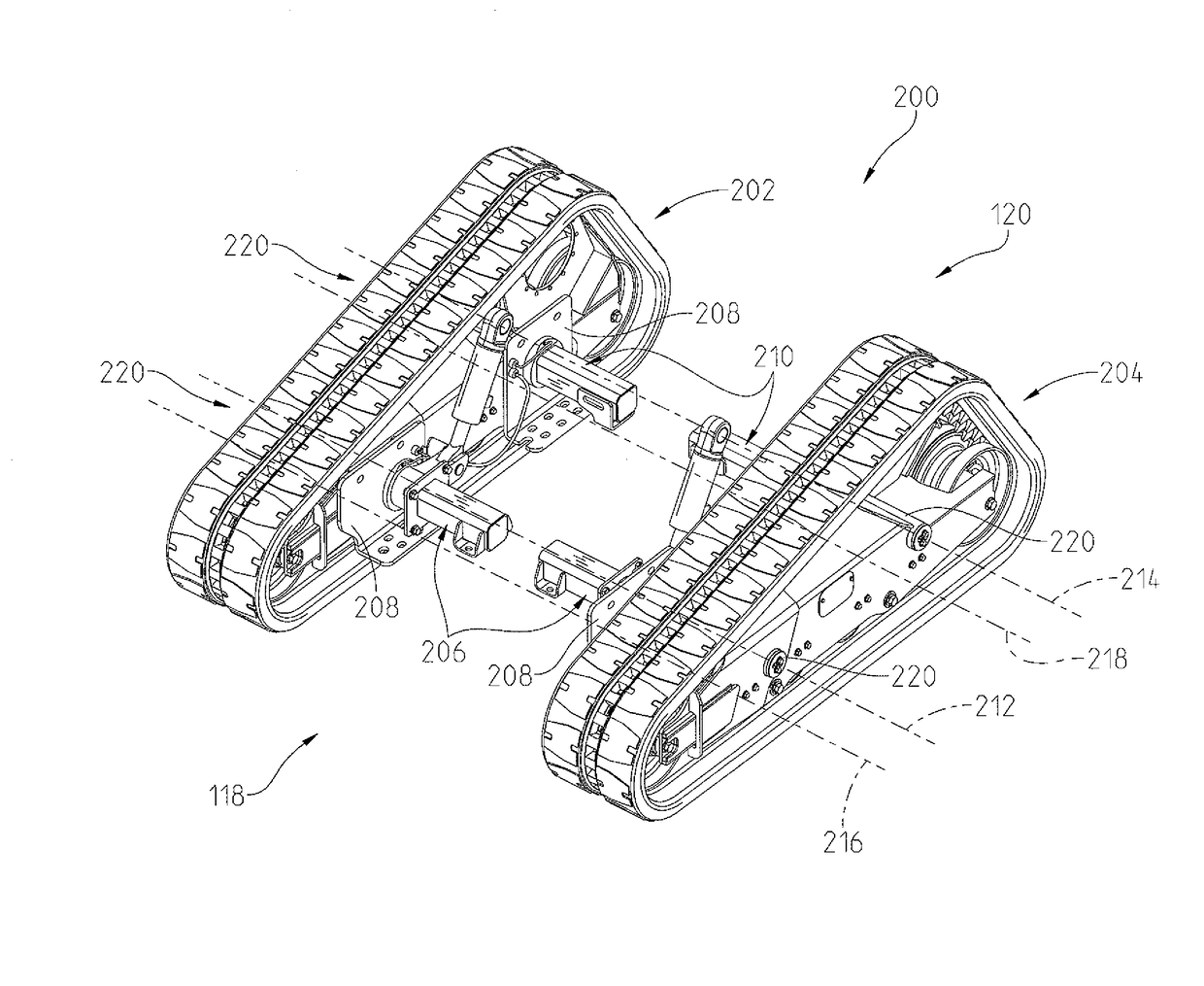
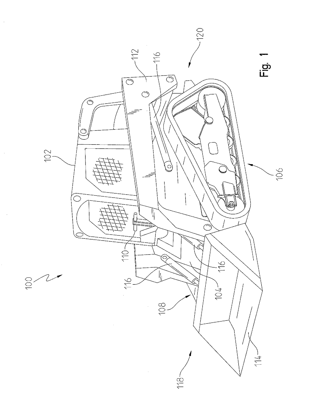
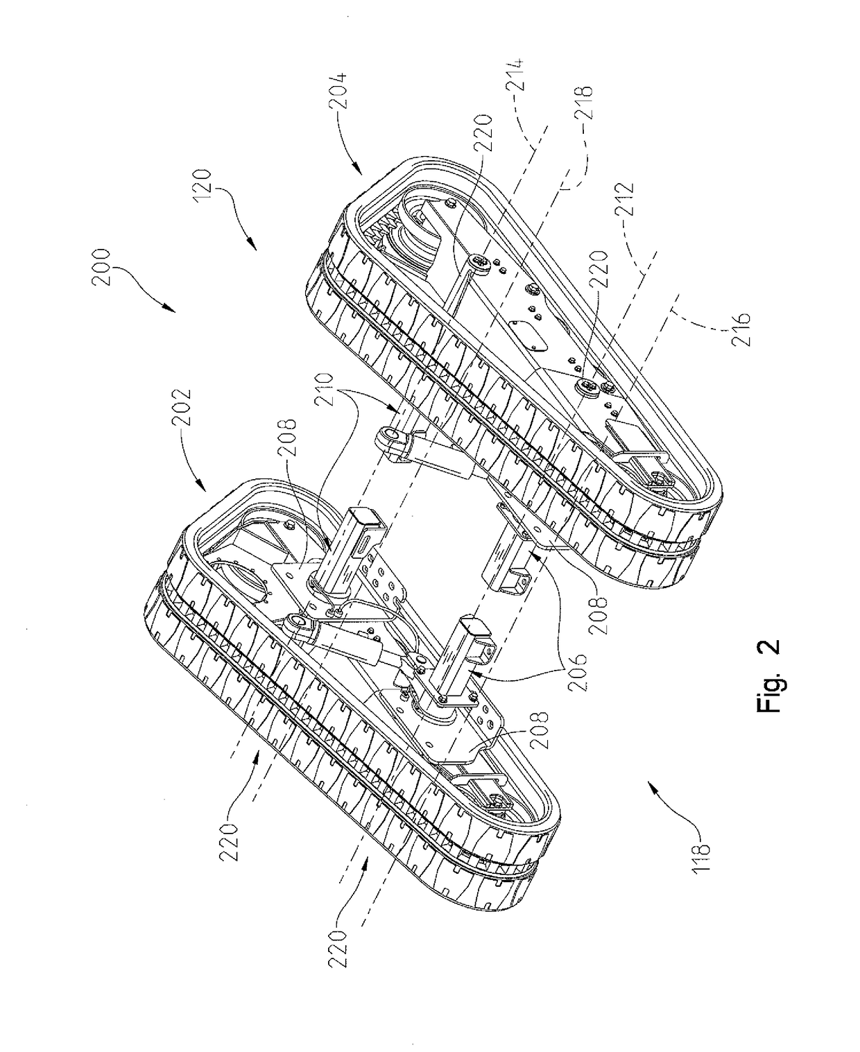
[0020]Referring now to FIG. 1, a compact track loader or work machine 100 is shown. The work machine 100 may have a front portion 118, a rear portion 120, and a cab 102 coupled to a frame 104. Also coupled to the frame 104 may be a first track assembly 106 and a second track assembly 108. An operator may be positioned in the cab 102 and have access to a plurality of controls 110. The plurality of controls may include joysticks, levers, wheels, push buttons, switches, knobs, dials, and any other known control mechanism for controlling a function of the machine 100. Further, the first and second track assembly 106, 108 may be selectively ...


PUM


Abstract

A suspension assembly of a work machine being movable in a forward direction. The work machine includes a frame, an undercarriage supporting the frame and at least one ground-engaging track. The suspension assembly includes a torsion assembly having an axle, a torsion bar adapted to be fixedly coupled to the frame, and an axle arm coupled at one end to the axle and at an opposite end thereof to the torsion bar. A locking arm has a first end and a second end, where the first end is coupled to the axle arm. A hydraulic actuator is coupled to the second end of the locking arm. The hydraulic actuator is operably controlled between a locked configuration and an unlocked configuration. In the unlocked configuration, the axle arm is pivotable relative to the frame, and in the locked configuration the axle arm is restricted from pivoting relative to the frame.

Description

FIELD OF THE DISCLOSURE[0001]The present disclosure relates to a suspension system, and in particular, to a suspension system of a work machine that can be locked or unlocked based on application.BACKGROUND OF THE DISCLOSURE[0002]Compact track loaders or other work machines often have at least one implement that is controlled by an operator. The implement can be a plurality of different devices such as a backhoe or a bucket to name a few. It is often desired to have a rigid connection with an underlying surface if the implement is going to maneuver a payload. More specifically, to provide the best possible control of the implement, the work machine should not substantially move when the implement is manipulating the payload. If the work machine utilizes tracks to travel along the underlying surface, sometimes the tracks are rigidly mounted to a frame of the work machine to inhibit movement of the work machine when the implement is being used. Similarly, work machines often have whee...

Claims


Application Information

Patent Timeline
IPC IPC(8): B62D55/108E02F9/20E02F3/34
CPCB62D55/1083E02F9/2025E02F3/3414E02F9/00E02F9/02E02F9/166E02F9/2207B62D55/06
Inventor THOMAS, GALEN C.WHITEMAN, STEVEN R.FLEISCHMANN, STEVE G.GROSS, JUSTIN C.WENTZLOFF, JAMES
Owner DEERE & CO
Why Eureka
Try Eureka