Liquid crystal display panel and liquid crystal display device

a liquid crystal display panel and liquid crystal display technology, applied in non-linear optics, instruments, optics, etc., can solve the problems of insufficient utilization of blue light, large amount of light loss, and insufficient absorbing of fluorescent powder, so as to improve the utilization ratio of blue light, improve the color gamut display quality and image display quality of the liquid crystal display panel.

Inactive Publication Date: 2017-04-13
WUHAN CHINA STAR OPTOELECTRONICS TECH CO LTD
View PDF4 Cites 8 Cited by
  • Summary
  • Abstract
  • Description
  • Claims
  • Application Information

AI Technical Summary

Benefits of technology

[0008]According to the present disclosure, the upper glass substrate and the lower glass substrate are provided with the first optical filter layers and the second optical filter layers respectively at positions corresponding to the red color-resist region and the green color-resist region, so that the blue light that is emitted by the backlight source can be prevented from exiting from the upper glass substrate through color-resist regions thereof with the cooperation of the first optical filter layers and the second optical filter layers. In this case, only light with a color the same as that of a color-resist region can exit from said color-resist region, and the light which exits from the color-resist region with a corresponding color can mix with the blue light which exits from the transparent region directly so as to form white light for image displaying. Compared with the traditional display panel, in the display panel according to the present disclosure, no blue light can exit from the color-resist region of the upper glass substrate, so that the utilization ratio of the blue light can be improved, and thus the color gamut display quality and the image display quality of the liquid crystal display panel can both be improved.
[0018]Compared with the prior art, in the liquid crystal display panel according to the present disclosure, no blue light can exit from the color-resist regions of the upper glass substrate with the cooperation of the first optical filter layer and the second optical filter layer. Therefore, the utilization ratio of the blue light can be improved, and thus the color gamut display quality and the image display quality of the liquid crystal display panel can both be improved. Moreover, according to the present disclosure, since the black matrix is provided with the reflection layer on the surface thereof, the light utilization ratio can be further improved while the color gamut display quality and the image display quality of the liquid crystal display panel would not be affected.

Problems solved by technology

As a result, a penetration ratio of the light which is emitted by the white LED and which can transmit through the color filter is less than 30 percent, and thus a large amount of light loss would be generated.
However, in this kind of liquid crystal display device, when blue light irradiates the red fluorescent powder or the green fluorescent powder, it can hardly be absorbed by the fluorescent powder sufficiently, and part of blue light would exit from a light-exiting surface of the glass substrate through the fluorescent powder.
As a result, the blue light cannot be utilized fully due to the aforesaid leakage.
The blue light that exits from the light-exiting surface of the glass substrate would mix with the red light or the green light that exits from the fluorescent powder with a corresponding color, and consequently, the color gamut display quality and the image display quality of the liquid crystal display panel would both be suffered.

Method used


Image

  • Liquid crystal display panel and liquid crystal display device
  • Liquid crystal display panel and liquid crystal display device

Examples


Embodiment Construction

[0022]The present disclosure will be further illustrated hereinafter with reference to the drawings.

[0023]The details described herein are only specific examples used for discussing the implementations of the present disclosure. The most useful and most understandable description on the principle and concept of the present disclosure is provided. The structural details which go beyond the scope of basic understanding of the present disclosure are not provided herein. Therefore, those skilled in the art can clearly understand, based on the description and the accompanying drawings, how to implement the present disclosure in different ways.

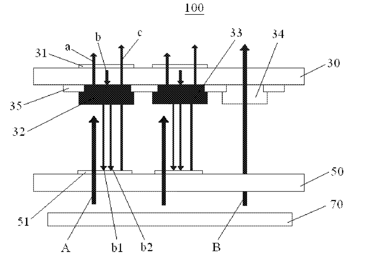
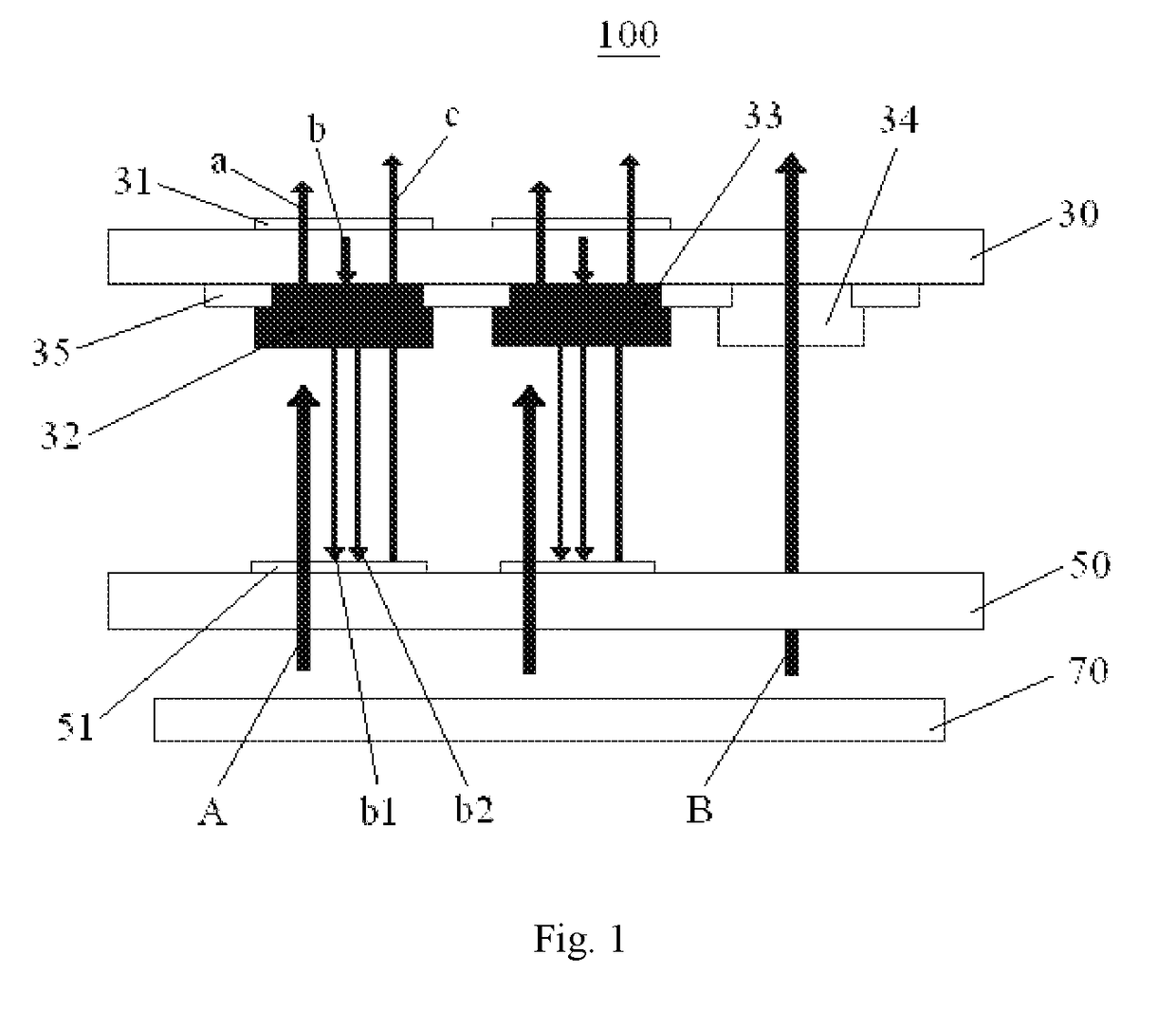
[0024]FIG. 1 schematically shows a structure of a liquid crystal display panel 100 according to the present disclosure. The liquid crystal display panel 100 comprises an upper glass substrate 30 and a lower glass substrate 50 that are arranged opposite to each other, and a backlight source 70 that is arranged below the lower glass substrate 50 and u...


PUM

PropertyMeasurementUnit
transparentaaaaaaaaaa
coloraaaaaaaaaa
colorsaaaaaaaaaa

Abstract

According to the present disclosure, the liquid crystal display panel comprises an upper glass substrate, a lower glass substrate, and a blue backlight source. The upper glass substrate comprises a plurality of color-resist units, each color-resist unit comprising a red color-resist region, a green color-resist region, and a transparent region that are arranged spaced from one another, black matrixes that are arranged between each two adjacent regions, and first optical filter layers that are arranged on an outer surface of the upper glass substrate at positions corresponding to the red color-resist region and the green color-resist region. The lower glass substrate comprises second optical filter layers at positions corresponding to the red color-resist region and the green color-resist region. According to the present disclosure, the image display quality of the liquid crystal display panel can be further improved.

Description

CROSS REFERENCE TO RELATED APPLICATION[0001]The present application claims the priority of Chinese patent application CN 201510201024.8, entitled “Liquid Crystal Display Panel and Liquid Crystal Display Device” and filed on Apr. 24, 2015, the entirety of which is incorporated herein by reference.FIELD OF THE INVENTION[0002]The present disclosure relates to the technical field of liquid crystal display, and particularly to a liquid crystal display panel and a liquid crystal display device.BACKROUND OF THE INVENTION[0003]In one kind of liquid crystal display device in the prior art, color filters are provided on a liquid crystal display panel, so that images can be displayed. In this kind of liquid crystal display device, a white Light-Emitting Diode (LED) generally serves as a light source thereof. When white light irradiates the color filters in the liquid crystal display panel, only red light, green light, and blue light can transmit through color filters with red color, green colo...

Claims


Application Information

Patent Timeline
Patent Type & Authority Applications(United States)
IPC IPC(8): G02F1/1335
CPCG02F1/133514G02F1/133512G02F1/133621G02F2001/133614G02F2203/055G02F2202/36G02F2001/133302G02F1/1336G02F1/133614G02F1/133516G02F1/133617G02F1/133302
Inventor WANG, JIANGFENG
Owner WUHAN CHINA STAR OPTOELECTRONICS TECH CO LTD
Why Eureka
Try Eureka