

Film forming method, film forming machine, device manufacturing method, apparatus and electronic equipment
A technology for equipment manufacturing and membrane devices, which is applied in the fields of membrane manufacturing and devices, equipment manufacturing and devices, equipment, and electronic equipment, and can solve problems such as adverse effects of membrane element characteristics and degradation of display quality
- Summary
- Abstract
- Description
- Claims
- Application Information
AI Technical Summary
Problems solved by technology
Method used
Image

Examples
Embodiment approach 1
[0046] First, the film forming apparatus included in the device manufacturing apparatus will be described.
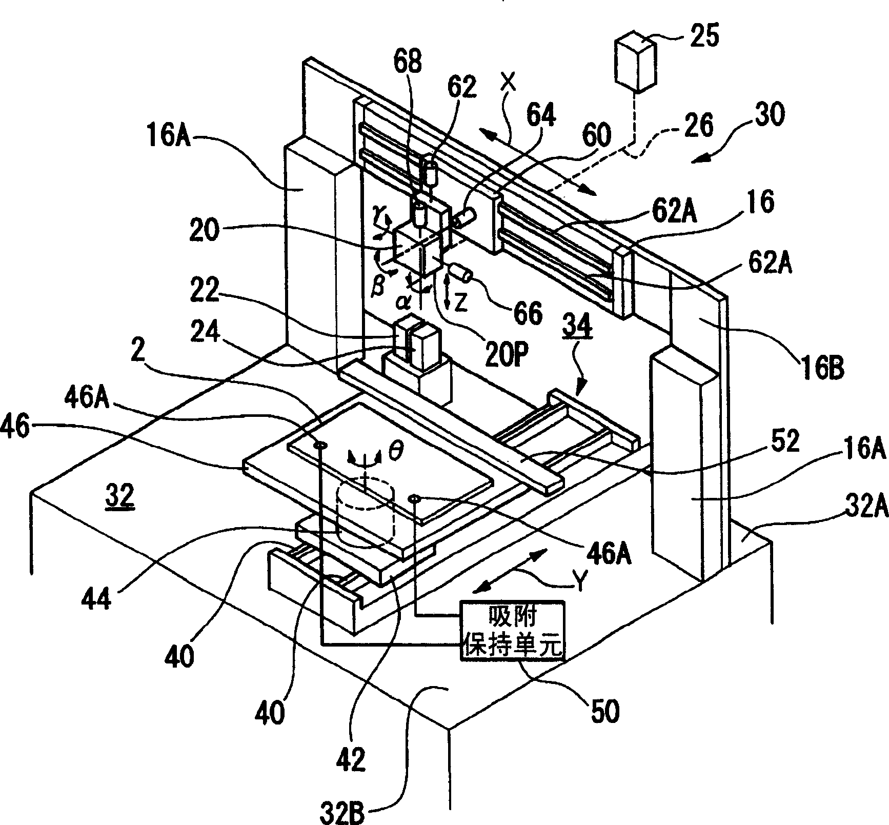
[0047] figure 1 It is a schematic external perspective view of a droplet application device 30 as a film forming device.
[0048] The droplet application device 30 has a base 32, a first moving unit 34, a second moving unit 16, an electronic balance (weight measurement unit) not shown in the figure, a droplet discharge head 20, a capping unit 22, and a cleaning unit 24. Wait. The first moving unit 34 , the electronic balance, the capping unit 22 , the cleaning unit 24 and the second moving unit 16 are all installed on the base 32 .
[0049]The first moving unit 34 is preferably provided directly on the base 32, and the position of the first moving unit 34 is determined on the Y axis. On the other hand, the second mobile unit 16 is installed standingly on the base 32 using the pillars 16A, 16A, and the second mobile unit 16 is attached to the rear portion 32A of the b...
Embodiment approach 2
[0080] In the first embodiment described above, the case of vibrating two kinds of liquid droplets 99a and 99b having different sizes at a constant frequency was described, but in the present embodiment, the case of vibrating by changing the frequency will be described.
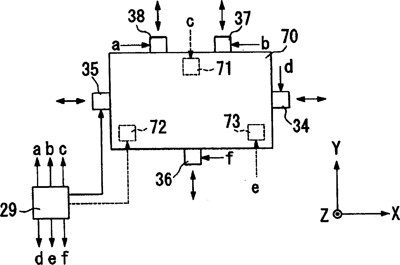
[0081] As shown in FIG. 8( a ), in this embodiment, liquid droplets 99 a to 99 c of three types of sizes (diameter 99 a > > 99 b > 99 c ) are coated on the substrate 2 . The control device 25 controls the driving of the piezoelectric elements 34-38, 71-73, including the natural vibration frequencies (resonant frequencies) fa, fb, fc corresponding to the sizes of the droplets 99a-99c respectively (knowing that fa< In the range of fb<fc), the frequency of the generated vibration is changed.
[0082] At this time, the control device 25 changes (sweeps) the frequency from high to low. In this case, first, the droplet 99c with the highest resonance frequency strongly vibrates (resonates), as shown in FIG. 8(b), f...
Embodiment approach 3
[0086] In Embodiment 3, a case where a linear film is formed by vibration will be described.
[0087] In the present embodiment, for example, as shown in FIG. 9( a), large-diameter droplet groups (first liquid droplets) are coated with various sizes (at least adjacent droplet sizes are different) along the X-axis direction (first direction). droplet group) 97a, on both sides of the Y direction that clamp the droplet group 97a, droplet groups with small diameters are applied in various sizes (at least adjacent droplet sizes are different) along the Y-axis direction (second direction). (Second droplet group) 97b.
[0088] The size of droplet group 97a is selected from a predetermined range (first range) and applied, and the size of droplet group 97b is selected and applied from a range different from that of droplet group 97a (second range).
[0089] In addition, the sizes of at least adjacent droplets in the droplet groups 97a and 97b are different, but in FIG. 9( a ), for con...
PUM
 Abstract
Description
Claims
Application Information