
A monitoring unit as well as method for predicting abnormal operation of time-triggered computer systems

a computer system and monitoring unit technology, applied in the direction of program control, non-redundant fault processing, program initiation/switch, etc., can solve problems such as program changes, errors that go undetected, and may already have been done a great deal of damage, and provide little or no protection against programming errors (including residual errors)

Inactive Publication Date: 2017-04-13
SAFETTY SYST
View PDF6 Cites 10 Cited by
  • Summary
  • Abstract
  • Description
  • Claims
  • Application Information

AI Technical Summary

Benefits of technology

[0018]In accordance with this aspect of the invention, a computer system is provided that executes scheduled tasks with a reduced likelihood of a critical failure.
[0023]The Monitor Processor is arranged to obtain information from the Main Processor about at least some of the tasks that the Main Processor plans to execute, before the tasks concerned are executed. This enables the Monitor Processor to determine in advance whether the Main Processor is about to execute a critical task that is not in accordance with the active task schedule. This provides the Monitor Processor with an opportunity to take appropriate corrective action, by virtue of a Control Mechanism, before the Main Processor executes a task that is not in accordance with the active task schedule. Such corrective action may—for example—include halting the Main Processor: when the Main Processor halts, this means that it will stop operating and will remain in a fixed state, typically until outside intervention occurs (for example, intervention by a trained operator). Alternatively, such corrective action may—for example—include resetting the Main Processor: when the Main Processor resets, this means that it will begin its operations again, from a known initial state. Further alternatively, such corrective action may include disabling devices that are under the control of the Main Processor: for example, this might mean removing power from a medical device that is being controlled by the Main Processor, thereby preventing harm to a patient.
[0030]Optionally, one or more of the tasks executing on the Main Processor will have been “balanced”, to ensure that the task execution time is approximately the same every time the task is executed.

Problems solved by technology

In most (but not all) cases, the lockstep solution will involve two or more processor units in close proximity: this gives rise to concerns about common-mode faults: for example, physical damage, vibration, humidity or radiation sources may have a similar impact on all processor units, causing errors to go undetected.
If we can avoid such common-mode failures, lockstep processors may allow us to detect the impact of some errors (including, potentially, the impact of EMI), but they provide little or no protection against programming errors (including residual errors), or program changes (caused, for example, by viruses or deliberate tampering).
Such watchdogs typically enforce a system halt or reset if they are not “fed” at the required frequency (and it is assumed—often implicitly—that system errors will interfere with this feeding process).
By the time such changes are significant enough to be detected, a great deal of damage may already have been done.
Late detection of errors in aerospace systems, industrial systems, defence systems, medical systems, financial systems or even household goods may also result in injury, loss of human life and / or very significant financial losses.

Method used


Image

  • A monitoring unit as well as method for predicting abnormal operation of time-triggered computer systems
  • A monitoring unit as well as method for predicting abnormal operation of time-triggered computer systems
  • A monitoring unit as well as method for predicting abnormal operation of time-triggered computer systems

Examples


Embodiment Construction

[0085]We begin by describing some existing techniques that are employed to create computer systems that execute tasks according to a predetermined task schedule. We then go on to describe how the present invention can be used to improve the reliability and security of such computer systems.

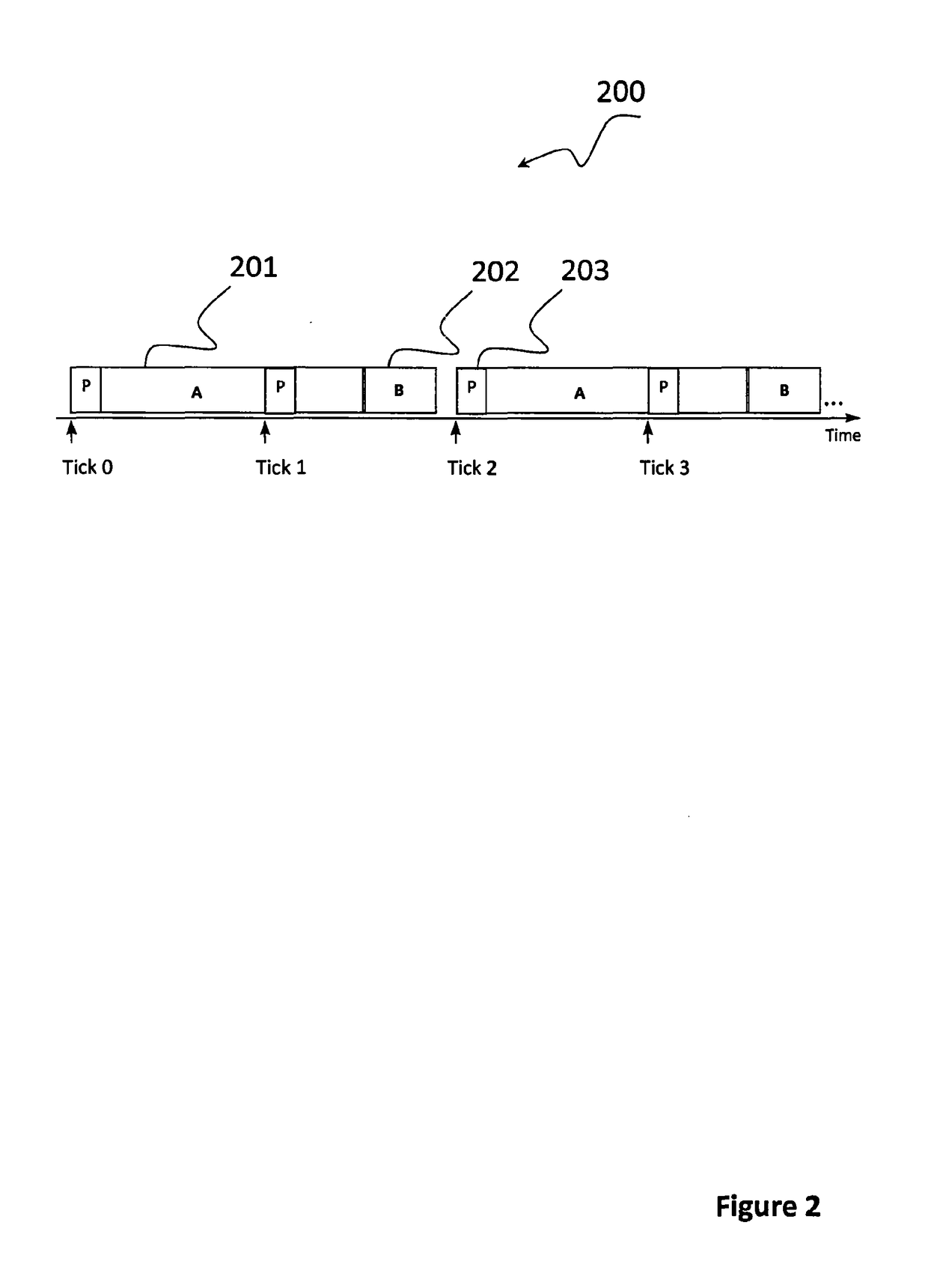
[0086]Computer systems that execute tasks according to a predetermined task schedule are sometimes referred to as time-triggered (TT) systems. TT systems are typically (but not necessarily) implemented using a design based on a single interrupt linked to the periodic overflow of a timer.

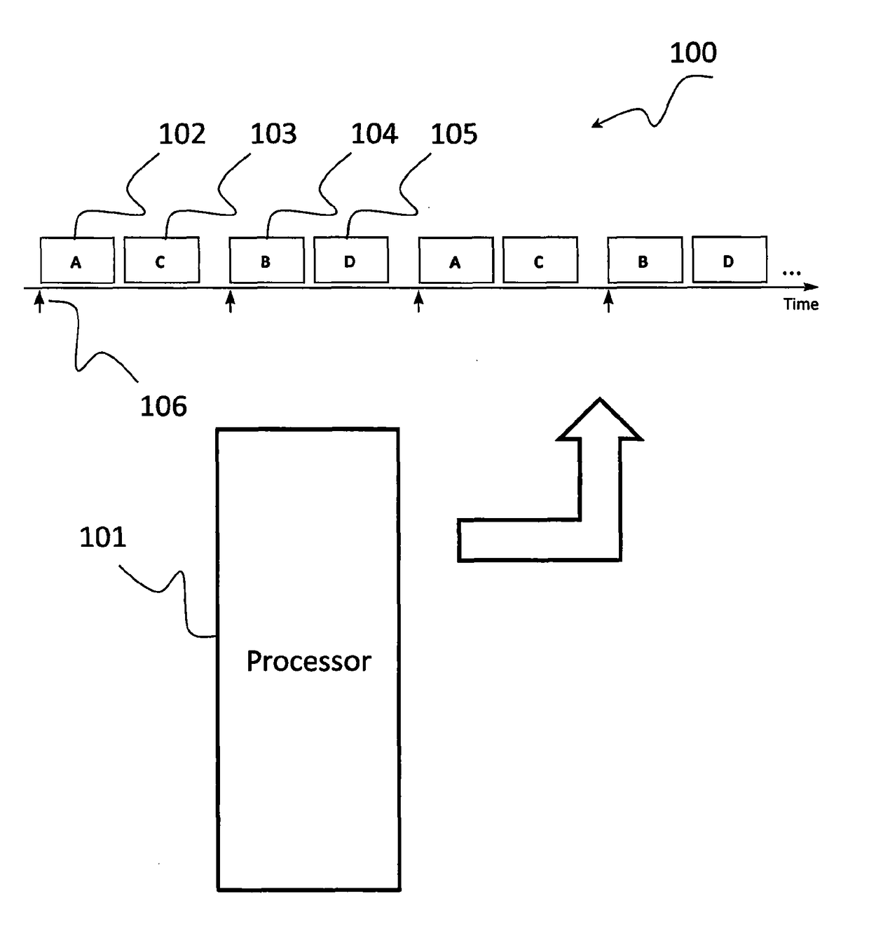
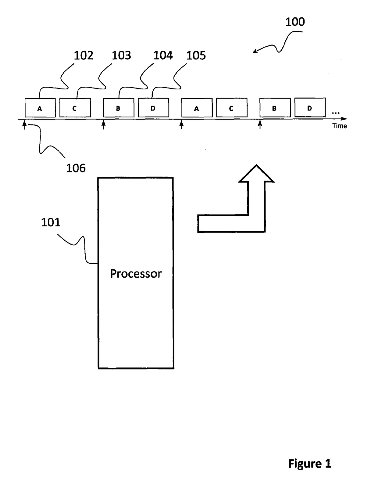
[0087]For example, FIG. 1 shows a TT computer system 100 made up of a Main Processor 101 that is executing a set of software tasks (in this case Task A 102, Task B 103, Task C 104 and Task D 105) according to a predetermined task schedule. In FIG. 1, the release of each sub-group of tasks (for example, Task A 102 and Task B 103) is triggered by what is usually called a “Timer Tick”106. The Timer Tick 106 is usually...


PUM


Abstract

The invention relates to a time-triggered computer system (800) that involves [i] a Main Processor (801) that has been designed to run one or more tasks according to one or more predetermined task schedules, only one of which, the “active task schedule”, will be active at any point in time; [ii] a Monitor Processor (802) that has been designed to determine whether the Main Processor (801) is about to execute a task that is not in accordance with the active task schedule; [iii] a Communication Link (803) for passing information about future task executions between the Main Processor (801) and the Monitor Processor (802); and [iv] a Control Mechanism (comprising a System Control output (805), and / or a Communication Link B (806), and / or a Reset Link (807)) by means of which the Monitor Processor can halt or reset the Main Processor and take other corrective actions involving devices to which the computer system is connected, if the Monitor Processor determines that the Main Processor is about to execute a task that is not in accordance with the active schedule.

Description

FIELD OF THE INVENTION[0001]The present invention relates to an apparatus and a method which provides improved reliability and security for computer systems. In particular, the present invention relates to a monitoring unit for predicting abnormal operation of a time-triggered computer system, and a method of providing such a monitoring unit.BACKGROUND TO THE INVENTION[0002]A computer system is usually comprised of one or more “Commercial Off The Shelf” (COTS) processors—for example, microcontrollers or microprocessors—and some software that will execute on such processor(s): this software may be created, for example, using a programming language such as ‘C’ or Ada.[0003]In many cases, processors are “embedded” inside larger systems, including cars, aircraft, industrial and agricultural machinery, medical equipment, white and brown goods and even in toys. It is estimated that people in the developed world encounter around 300 of such “embedded systems” every day while going about th...

Claims


Application Information

Patent Timeline
Patent Type & Authority Applications(United States)
IPC IPC(8): G06F9/48G06F11/34G06F11/30
CPCG06F9/4887G06F11/3495G06F11/3024G06F11/0739G06F11/0757G06F11/0793G06F11/0703G06F11/0721G06F11/0733G06F11/30
Inventor PONT, MICHAEL JOSEPH
Owner SAFETTY SYST
Learn More