Laminated battery, separator and connection method of internal resistance measuring device

Active Publication Date: 2017-04-13
NISSAN MOTOR CO LTD
View PDF2 Cites 2 Cited by
  • Summary
  • Abstract
  • Description
  • Claims
  • Application Information

AI Technical Summary

Benefits of technology

[0003]However, the conventional internal resistance measuring device of the laminated battery described above has not taken into account the effect of a voltage drop caused in a non-power generation region of the separator from the sense line to the

Problems solved by technology

However, the conventional internal resistance measuring device of the laminated battery described above has not taken into account the effect of a voltage drop caused in a non-power generation region of the separator from the sense line to the power generation region of the separator.
Thus, the alternating-current potential inp

Method used


Image

  • Laminated battery, separator and connection method of internal resistance measuring device
  • Laminated battery, separator and connection method of internal resistance measuring device
  • Laminated battery, separator and connection method of internal resistance measuring device

Examples


Example

First Embodiment

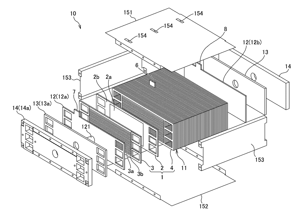
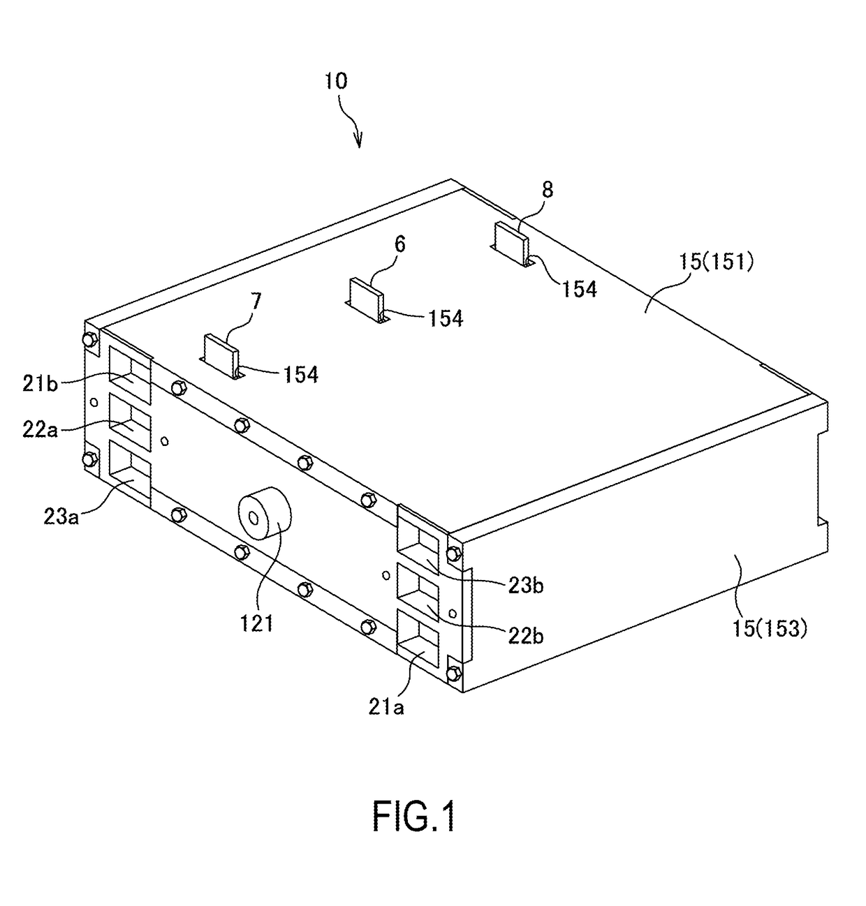
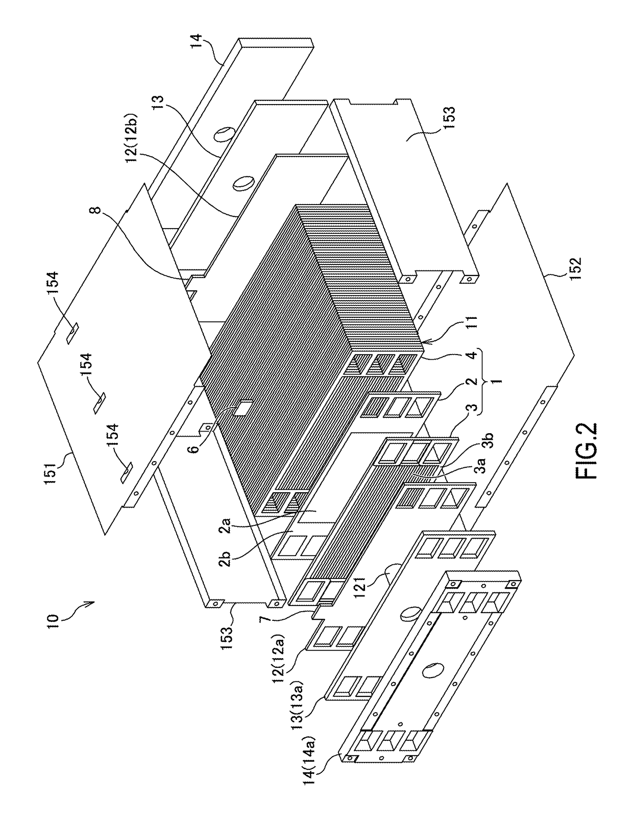
[0030]FIG. 1 is a perspective view of a fuel cell stack 10 according to a first embodiment of the present invention. FIG. 2 is an exploded perspective view of the fuel cell stack 10.

[0031]As shown in FIGS. 1 and 2, the fuel cell stack 10 includes a laminated battery 11, a pair of current collector plates 12, a pair of insulating plates 13, a pair of end plates 14 and a casing 15.

[0032]The laminated battery 11 is such that a plurality of fuel cells 1 are laminated and connected in series.

[0033]The fuel cell 1 is, for example, a unit cell of a solid polymer type fuel battery. As shown in FIG. 2, the fuel cell 1 includes a MEA plate 2 in which a membrane electrode assembly (hereinafter, referred to as “MEA”) 2a is arranged in a central part, a cathode separator 3 arranged on one surface side (front side in FIG. 2) of the MEA plate 2 and an anode separator 4 arranged on the other surface side (back side in FIG. 2) of the MEA plate 2.

[0034]The MEA 2a arranged in the centr...

Example

Second Embodiment

[0138]Next, a second embodiment of the present invention is described with reference to FIG. 11. The second embodiment of the present invention differs from the first embodiment in the shape of an intermediate tab 6. The following description is centered on that point of difference. It should be noted that, in each of the following embodiments, parts having the same functions as in the aforementioned first embodiment are denoted by the same reference signs and repeated description is omitted as appropriate.

[0139]FIG. 11 is a schematic diagram of a part of an intermediate separator 3 according to the present embodiment showing flows of alternating currents input and output to and from the intermediate tab 6.

[0140]As shown in FIG. 11, in the present embodiment, a vertical width (projecting width from the separator) of the intermediate tab 6 is shorter than in the first embodiment and a lateral width of the intermediate tab 6 is widened toward a power generation region...

Example

Third Embodiment

[0144]Next, a third embodiment of the present invention is described with reference to FIG. 12. The third embodiment of the present invention differs from the first embodiment in the shape of an intermediate tab 6. The following description is centered on that point of difference.

[0145]FIG. 12 is a schematic diagram of a part of an intermediate separator 3 according to the present embodiment showing flows of alternating currents input and output to and from the intermediate tab 6.

[0146]As shown in FIG. 12, in the present embodiment, a vertical width (projecting width from the separator) of the intermediate tab 6 is shorter than in the first embodiment and a lateral width of the intermediate tab 6 is widened toward a non-power generation region 3b.

[0147]This enables an intermediate sense connection point 62 to be more distanced from the power generation region 3a and a distance between the intermediate sense connection point 62 and the power generation region 3a to b...


PUM


Abstract

A separator of a fuel cell to be laminated while sandwiching a membrane electrode assembly forming a power generation region includes a source connection point tab for inputting and outputting an alternating current for internal resistance measurement, a sense connection point tab for detecting a potential of the alternating current input and output to and from the source connection point tab and separation portion configured to separate the sense connection point tab from a current path of the alternating current for internal resistance measurement from the source connection point tab to the power generation region.

Description

TECHNICAL FIELD[0001]The present invention relates to a laminated battery, a separator and a connection method of an internal resistance measuring device.BACKGROUND ART[0002]It is disposed in WO2012 / 077450A1 to connect, as a conventional internal resistance measuring device of a laminated battery, a source line and a sense line to a separator of a laminated battery in different paths. This conventional internal resistance measuring device of the laminated battery has measured an internal resistance of the laminated battery by causing an alternating current to flow in a power generation region of the separator via the source line and inputting an alternating-current potential at that time to the internal resistance measuring device via the sense line.SUMMARY OF INVENTION[0003]However, the conventional internal resistance measuring device of the laminated battery described above has not taken into account the effect of a voltage drop caused in a non-power generation region of the sepa...

Claims


Application Information

Patent Timeline
IPC IPC(8): H01M8/04537H01M8/242H01M8/1004H01M8/0202
CPCH01M8/04649H01M8/0202H01M2008/1095H01M8/242H01M8/1004H01M8/04589H01M8/0267H01M8/2483Y02E60/50G01R31/389H01M8/241
Inventor AOKI, TETSUYASAKAI, MASANOBUSUGIMOTO, KEI
Owner NISSAN MOTOR CO LTD
Why Eureka
Try Eureka