
Method and apparatus for producing a three-dimensional article

a three-dimensional object and apparatus technology, applied in the direction of additive manufacturing processes, manufacturing tools, applying layer means, etc., can solve the problems of deteriorating the surface finish, consuming relative space, and creating unnecessary force on the powder distributor, so as to improve the exact amount of powder

Active Publication Date: 2017-04-20
ARCAM AB
View PDF7 Cites 54 Cited by
  • Summary
  • Abstract
  • Description
  • Claims
  • Application Information

AI Technical Summary

Benefits of technology

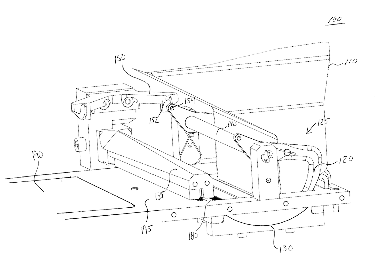
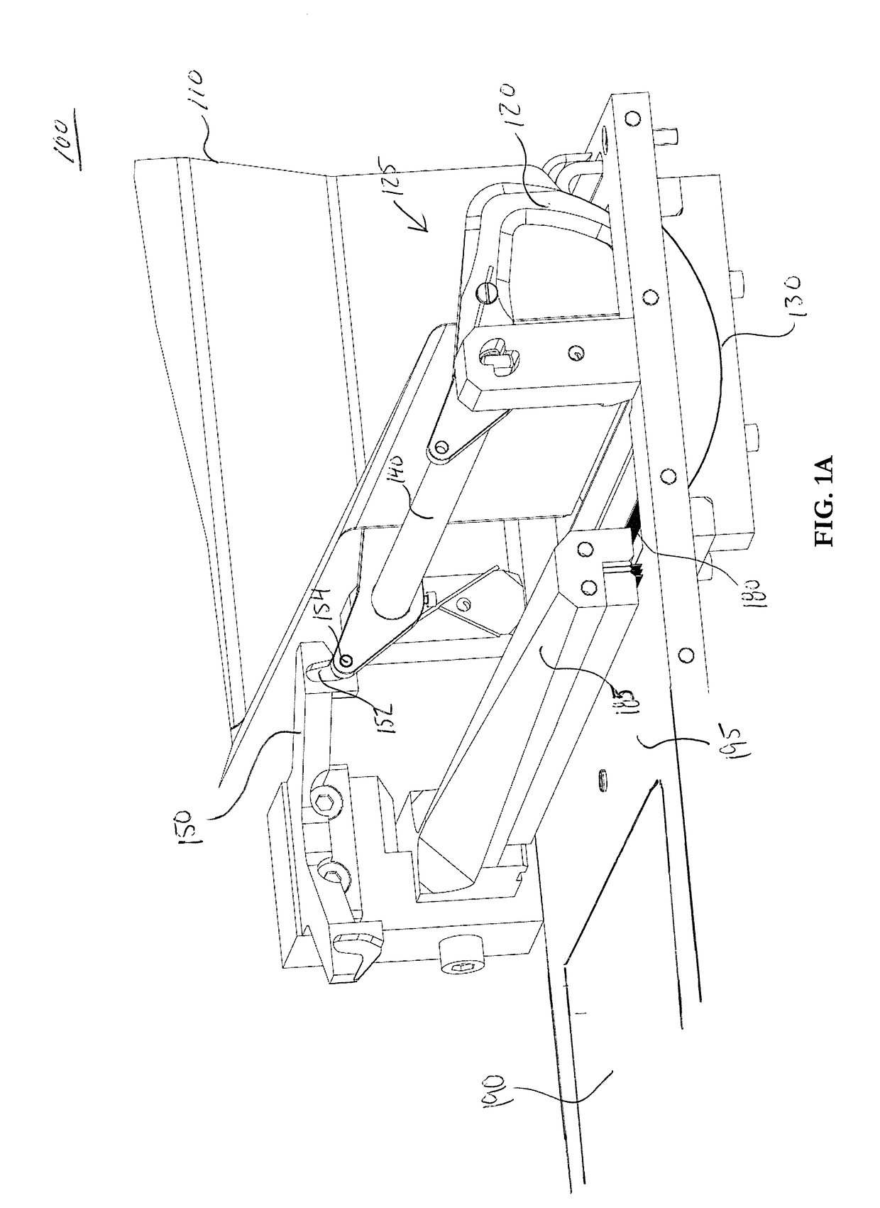
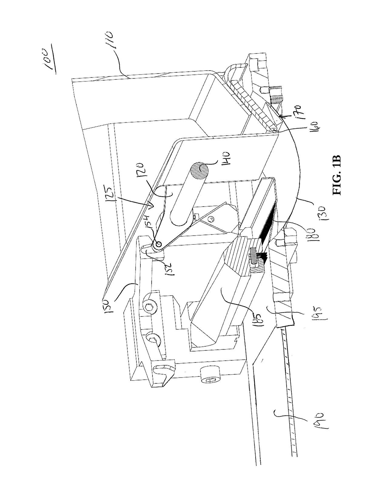
The present invention provides an improved design for a powder transfer apparatus that allows for better control of the size of the powder portion being transferred, even when using powder with poor flowability. This is achieved through a pivoted powder pushing device that decouples the physical contact of the powder portion and the powder distributor until the powder portion is actually formed as a layer. The apparatus is less sensitive to the type of powder being provided in front of the distributor, meaning that the size of the powder portion transferred can be controlled in a more exact manner. Additionally, the apparatus may not require a powder sensor to measure the amount of powder being distributed on the working area. The design of the rake may also be used in various embodiments. The powder supply base surface may have a curved shape to improve the exactness of the amount of powder to be delivered onto the powder table.

Problems solved by technology

A drawback of such systems is that it is relatively space consuming.
Problems may arise with the device disclosed in WO 2006 / 121374 when using certain types of powder that do not flow very well.
A drawback with this design is that the rake has to move into the powder supply which creates unnecessary force on the powder distributor.
Another problem is that powder may stick on the back side of the powder distributor which may fall off on a newly distributed powder layer and thereby deteriorate its surface finish.

Method used


Image

  • Method and apparatus for producing a three-dimensional article
  • Method and apparatus for producing a three-dimensional article
  • Method and apparatus for producing a three-dimensional article

Examples


Embodiment Construction

[0039]To facilitate the understanding of this invention, a number of terms are defined below. Terms defined herein have meanings as commonly understood by a person of ordinary skill in the areas relevant to the present invention.

[0040]Terms such as “a”, “an” and “the” are not intended to refer to only a singular entity, but include the general class of which a specific example may be used for illustration. The terminology herein is used to describe specific embodiments of the invention, but their usage does not delimit the invention, except as outlined in the claims.

[0041]The term “three-dimensional structures” and the like as used herein refer generally to intended or actually fabricated three-dimensional configurations (e.g. of structural material or materials) that are intended to be used for a particular purpose. Such structures, etc. may, for example, be designed with the aid of a three-dimensional CAD system.

[0042]The term “electron beam” as used herein in various embodiments ...


PUM

PropertyMeasurementUnit
Flow rateaaaaaaaaaa
Shapeaaaaaaaaaa
Areaaaaaaaaaaa

Abstract

Apparatus for producing a three-dimensional object layer by layer using a powdery material which can be solidified by irradiating it with an energy beam, said apparatus comprising: a working area onto which layers of powdery material are to be placed; a powder storage unit, where said base surface is supporting a supply of powder in said powder storage unit; a powder distribution member, a pivoted powder pushing device for bringing a portion of powder from said base surface to a position between said distribution member and said working area, said distribution member further being arranged to be moveable towards and across the working area so as to distribute the portion of powder onto the working area, wherein a first portion of said pivoted powder pushing device is movable under said distribution member. An associated method and computer program product are also provided.

Description

CROSS-REFERENCE TO RELATED APPLICATIONS[0001]This application claims priority to and the benefit of U.S. Provisional Patent Application Ser. No. 62 / 241,950, filed Oct. 15, 2015; the contents of which as are hereby incorporated by reference in their entirety.BACKGROUND[0002]Technical Field[0003]This invention relates to a method and an apparatus for producing a three-dimensional object layer by layer using a powdery material which can be solidified by irradiating it with an energy beam. In particular, the invention relates to the layer-wise application of powder.[0004]Related Art[0005]Equipment for producing a three-dimensional object layer by layer using a powdery material which can be solidified by irradiating it with electromagnetic radiation or an electron beam are known from e.g. U.S. Pat. No. 4,863,538, U.S. Pat. No. 5,647,931 and SE524467. Such equipment include for instance a supply of powder, means for applying a layer of powder on a working area, and means for directing the...

Claims


Application Information

Patent Timeline
IPC IPC(8): B22F3/105B33Y30/00B23K26/70B23K15/00B23K15/02B23K26/342B33Y10/00B33Y50/02
CPCB22F3/1055B33Y10/00B33Y30/00B33Y50/02B22F2998/10B23K15/02B23K26/342B23K26/70B22F2003/1057B23K15/0086B29C64/153B22F2999/00B29C64/20Y02P10/25B22F10/28B22F12/226B22F12/50B22F12/67B22F3/004B29C64/218B29C64/205B29C64/321B29C64/329B29C64/214B22F3/105B29C64/255B29C64/209B29C64/259B22F10/10B22F12/00B29L2009/00
Inventor KARLSSON, KRISTOFER
Owner ARCAM AB
Learn More