Eureka AIR delivers breakthrough ideas for toughest innovation challenges, trusted by R&D personnel around the world.

Sensor module that switches plural sensors capable of measuring different ranges to extend dynamic range

Active Publication Date: 2017-04-20
ALPS ALPINE CO LTD
View PDF7 Cites 10 Cited by
  • Summary
  • Abstract
  • Description
  • Claims
  • Application Information

AI Technical Summary

Benefits of technology

The patent describes a system that uses two magnetic sensors to improve the signal-to-noise ratio and linearity in measuring small amounts of current. One sensor has low sensitivity, while the other has high sensitivity. By connecting the high-sensitivity sensor to an amplifier for a small current and the low-sensitivity sensor to an amplifier for a large current, the system can extend the dynamic range of the current sensor. This is useful for using sensors in current sensors that measure different ranges, allowing them to measure a wider range of current.

Problems solved by technology

Even in cases of sensors that measure any physical quantities (such as, for example, magnetism, current, voltage, power, electrical resistance, temperature, acceleration, velocity, illuminance, volume level, pressure, temperature, humidity, malodor, the sense of taste, vibration, length, liquid level, and flow rate), most of the sensors are of limited measurable range.
When the magnetic saturation is generated, the output level of the magnetic sensor decreases as described above, and thus an error is generated in the measurement result of a current.

Method used


Image

  • Sensor module that switches plural sensors capable of measuring different ranges to extend dynamic range
  • Sensor module that switches plural sensors capable of measuring different ranges to extend dynamic range
  • Sensor module that switches plural sensors capable of measuring different ranges to extend dynamic range

Examples


first embodiment

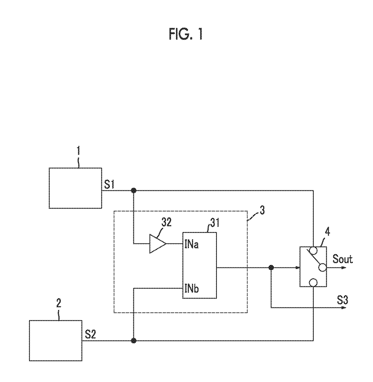
[0048]FIG. 1 is a diagram illustrating an example of a configuration of a sensor module according to a first embodiment of the present invention. This sensor module is a sensor module that measures a physical quantity through sensors (1 and 2), and switches between and uses two sensors (1 and 2) different from each other in sensitivity to a physical quantity in accordance with the range of measurement. Examples of physical quantities to be measured include magnetism, current, voltage, power, electrical resistance, temperature, acceleration, velocity, illuminance, volume level, pressure, humidity, malodor, the sense of taste, vibration, length, liquid level, and flow rate. Particularly, the details of a current sensor module using a magnetic sensor will be described later. In FIG. 1, configurations and operations which are applicable to even cases where any physical quantities are measured will be described.

[0049]The current sensor module shown in FIG. 1 includes a first sensor 1 and...

second embodiment

[0122]Next, a second embodiment of the present invention will be described.

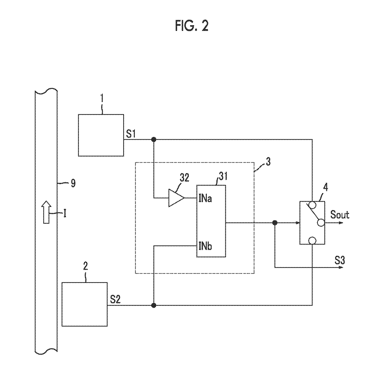
[0123]FIG. 5 is a diagram illustrating an example of a configuration of a current sensor module according to the second embodiment. The current sensor module shown in FIG. 5 has the same configuration as that of the current sensor module shown in FIG. 2, and includes a first low-pass filter 11 and a second low-pass filter 12.

[0124]The first low-pass filter 11 attenuates a high frequency component such as noise included in the output of the first magnetic sensor 1. The output of the first magnetic sensor 1 passes through the first low-pass filter 11 and is input to the selection unit 4 and the comparison unit 3.

[0125]The second low-pass filter 12 attenuates a high frequency component such as noise included in the output of the second magnetic sensor 2. The output of the second magnetic sensor 2 passes through the second low-pass filter 12 and is input to the selection unit 4 and the comparison unit 3.

[0126]Eac...

third embodiment

[0129]Next, a third embodiment of the present invention will be described.

[0130]FIG. 5 is a diagram illustrating an example of a configuration of a current sensor module according to the third embodiment. The current sensor module shown in FIG. 6 has the same configuration as that of the current sensor module shown in FIG. 2, and includes a first low-pass filter 11, the second low-pass filter 12, and an off-delay timer 5.

[0131]The first low-pass filter 11 and the second low-pass filter 12 are the same as the components denoted by the same reference numerals in the current sensor module shown in FIG. 5. However, the above current sensor module is different from the current sensor module shown in FIG. 5, in that the outputs of the first magnetic sensor 1 and the second magnetic sensor 2 are input to the comparison unit 3 without passing through these low-pass filters (11 and 12). That is, the comparison unit 3 compares the current level (first current level) of the current I to be mea...


PUM


Abstract

An output of a first sensor having a low sensitivity and an output of the second sensor having a high sensitivity are compared with each other, and thus it is determined whether a physical quantity becomes larger than a maximum value of a physical quantity capable of being measured in the second sensor. A sensor module is provided which is configured to switch a plurality of sensors capable of measuring different ranges and to extend a dynamic range by selecting the output of the second sensor in a selection unit in a case where the output of the first sensor and the output of the second sensor are coincident with each other, and selecting the output of the first sensor in the selection unit in a case where the output of the first sensor and the output of the second sensor are not coincident with each other.

Description

CLAIM OF PRIORITY[0001]This application is a Continuation of International Application No. PCT / JP2015 / 071812 filed Jul. 31, 2015, which claims priority to Japanese Patent Application No. 2014-159849 filed on Aug. 5, 2014, which are hereby incorporated by reference.BACKGROUND OF THE INVENTION[0002]1. Field of the Invention[0003]The present invention relates to a sensor module that switches a plurality of sensors capable of measuring different ranges to extend a dynamic range, and particularly relates to a technique suitable for a current sensor module using a plurality of magnetic sensors capable of measuring different magnitudes of magnetic fields.[0004]2. Description of the Related Art[0005]As a method of extending the range of measurement of a sensor, a method of switching sensors capable of detecting different magnitudes of physical quantities is generally known. In a sensitivity switching-type sensor circuit disclosed in U.S. Pat. No. 7,382,150 B2 described below, the voltages o...

Claims


Application Information

Patent Timeline
IPC IPC(8): G01R15/08G01R19/00
CPCG01R19/0092G01R15/08G01R15/09G01R15/207
Inventor HEBIGUCHI, HIROYUKI
Owner ALPS ALPINE CO LTD
Why Eureka
Eureka Blog
Learn More