Solid-state charge detector

US20210050200A1Active Publication Date: 2021-02-18BRIGHAM YOUNG UNIV

Image

  • Solid-state charge detector
  • Solid-state charge detector
  • Solid-state charge detector

Examples


Embodiment Construction

[0036]Reference will now be made to the drawings in which the various embodiments of the present invention will be discussed so as to enable one skilled in the art to make and use the invention. It is to be understood that the following description illustrates embodiments of the present invention and should not be viewed as narrowing the claims which follow.

[0037]To introduce the improvement over the prior art of charge detection, it is useful to understand the areas in which greatest improvement is achieved. In the context of IDELs, there may be three common barriers to ideal charge detector performance.

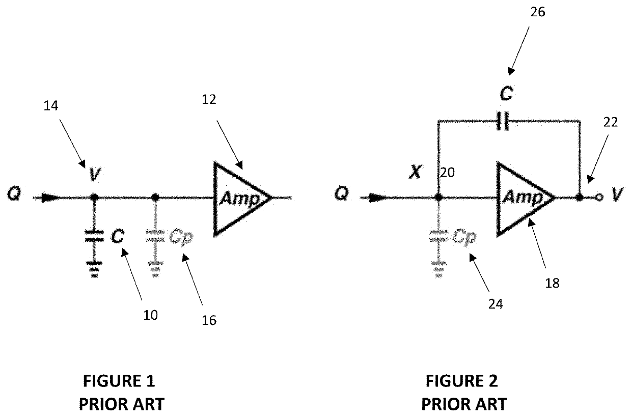
[0038]First, many amplifier circuits utilize a feedback capacitor to “collect” the incoming charge. It may be desirable to minimize the feedback capacitance so as to maximize the output voltage to thereby obtain a good signal-to-noise ratio (SNR). However, discrete capacitors available commercially are generally 0.1 pF or larger with impractically large specification tolerances of u...


PUM


Abstract

The present invention is a system and method for providing a charge detector that utilizes small feedback capacitors in a low-noise, high-gain, system that combines a differential topology in a solid-state amplifier implemented in a complementary metal-oxide semiconductor (CMOS) process with active reset, thereby achieving high dynamic range and robust operations. A custom optoelectronic system is used to measure gain, and while operating at a sampling frequency of 10 kHz, the active reset extends the dynamic range of the charge detector.

Description

CROSS-REFERENCE TO RELATED APPLICATIONS[0001]This application claims the benefit of U.S. Provisional Application No. 62 / 887,500 filed Aug. 15, 2019; U.S. Provisional Application No. 62 / 888,108 filed Aug. 16, 2019; and U.S. Provisional Application No. 62 / 916,071 filed Oct. 16, 2019, which are hereby incorporated by reference herein in their entireties, including but not limited to those portions that specifically appear hereinafter, the incorporation by reference being made with the following exception: In the event that any portion of the above-referenced applications are inconsistent with this application, this application supersedes said above-referenced applications.STATEMENT REGARDING FEDERALLY SPONSORED RESEARCH OR DEVELOPMENT[0002]The invention was made with government support under Grant Number 80NSSC17K0101 awarded by NASA. The government has certain rights in the invention.BACKGROUNDField of the Invention[0003]This invention relates generally to charge detection. More speci...

Claims


Application Information

Patent Timeline
18 Feb 2021
Publication
US20210050200A1
IPC
H01J49/02; G01R29/24; H03F3/45; H03F3/70; H03G3/30
CPC
H01J49/022; G01R29/24; H03G3/30; H03F3/45273; H03F3/70; H01J49/025; H03F3/45475; H03F3/45192
Inventors
SONG, YIXIN; CHIANG, SHIUH-HUA WOOD