Dynamic transaction card protected by dropped card detection

Active Publication Date: 2017-04-20
CAPITAL ONE SERVICES
View PDF0 Cites 149 Cited by
  • Summary
  • Abstract
  • Description
  • Claims
  • Application Information

AI Technical Summary

Benefits of technology

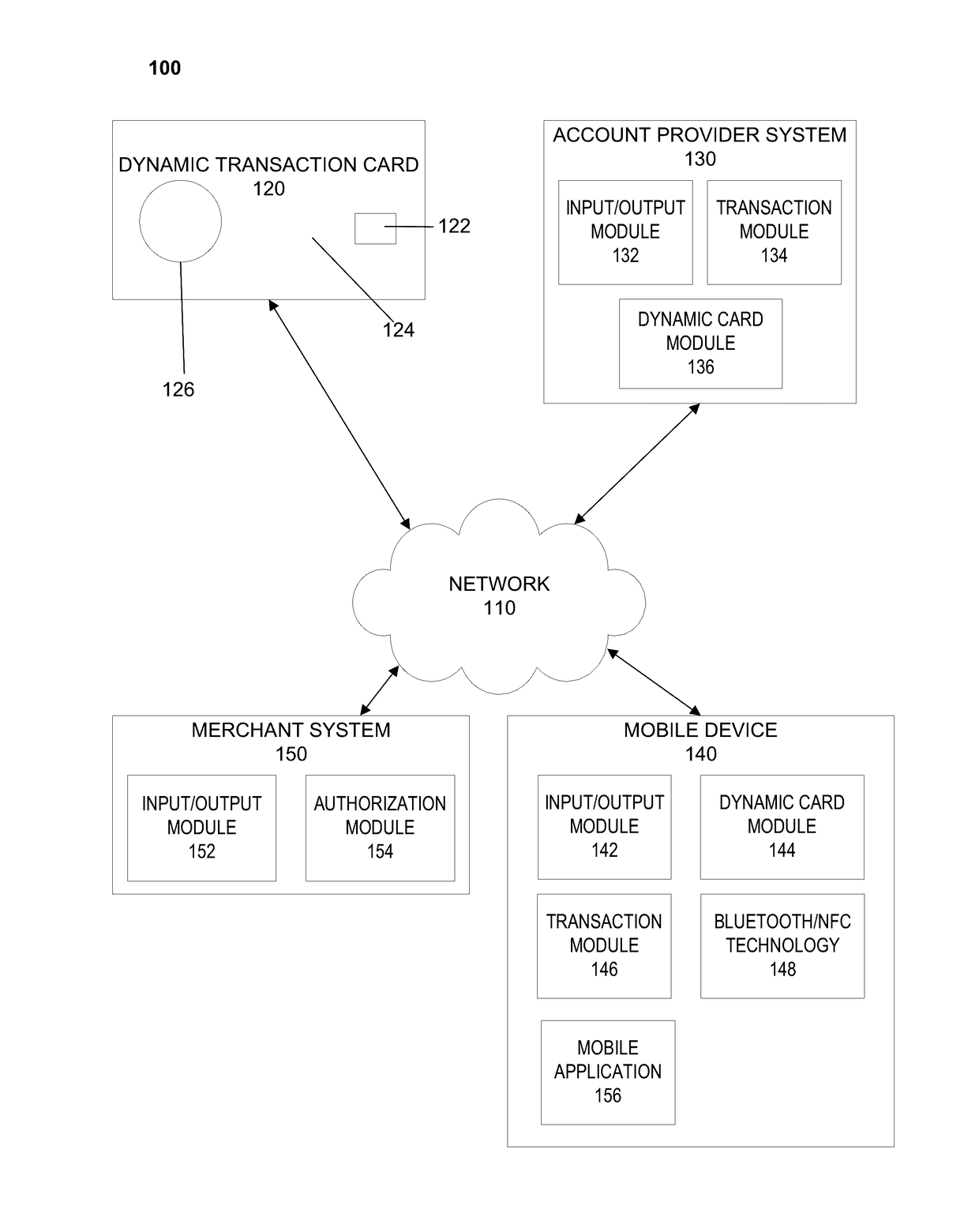
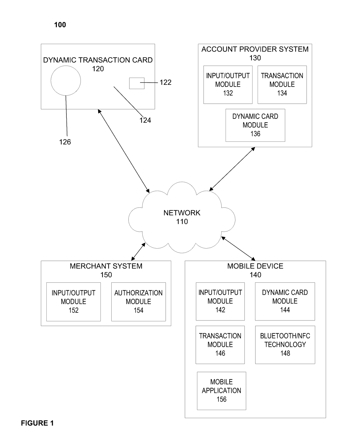
[0014]A dynamic transaction card may include a number of interactive components, including for example, components that may execute on a microprocessor, which may interact with an EMV™ chip via an Application Program Interface (API) defined for the EMV™ chip. By interacting with the EMV™ chip, the microprocessor could run applications, such as an application that allows a customer to select a particular financial account to use when executing a transaction, applications that alert a customer of an account balance, applications that allow a customer to view account information (e.g., recent transactions, spending per category, budgeting information, and/or the like), applications that allow customers to activate an additional account (e.g., where a customer has an existing debit account, that customer may activate a new credit account), and/or other applications that allow a customer to interact with an account and/or account data. By way of example, an application may allow a customer to select from a credit account, a savings account, a debit account, and/or the like, where each account has information regarding the account stored on the microprocessor. As described herein, an application may generate a display (e.g., dot matrix, LED display, OLED display, and/or the like) to illustrate various features of an account such as account data (e.g., account balance, account limit, transaction history, budget balance, budget limit, and/or the like) and

Problems solved by technology

Transaction cards, such as credit cards or debit cards, have limited capabilities.
However, EMV™ and magnetic stripe cards have limited capabilities, such as limited display capabilities, limited transaction capabilities, and limited processing capabilities, and limited security capabilities.
For example, when a smart card is dropped, there is no immediate way to detect that th

Method used


Image

  • Dynamic transaction card protected by dropped card detection
  • Dynamic transaction card protected by dropped card detection
  • Dynamic transaction card protected by dropped card detection

Examples


Embodiment Construction

[0043]The entire contents of the following applications are incorporated herein by reference: U.S. Provisional Application No. 62 / 266,324 entitled “Printed Circuit Board with Integrated Battery” filed Dec. 11, 2015; U.S. Provisional Application No. 62 / 270,307 entitled “Capacitive Powertrain for a Smart Card” filed Dec. 21, 2015; U.S. Provisional Application No. 62 / 305,599 entitled “Smart Card EuroPay Master Card Visa (“EMV”) Terminal Energy Harvesting” filed Mar. 9, 2016; U.S. patent application Ser. No. 14 / 977,730 entitled “A System, Method, and Apparatus for Locating a Bluetooth Enabled Transaction Card, filed Dec. 22, 2015, which claims the benefit of U.S. Provisional Application No. 62 / 095,190, filed on Dec. 22, 2014; U.S. Pat. No. 9,105,025, entitled, Enhanced Near Field Communications Attachment filed on May 29, 2014, which claims the benefit of U.S. Provisional Application No. 61 / 570,275 filed on Dec. 13, 2011 and U.S. Provisional Application No. 61 / 547,910 filed on Oct. 17, ...


PUM


Abstract

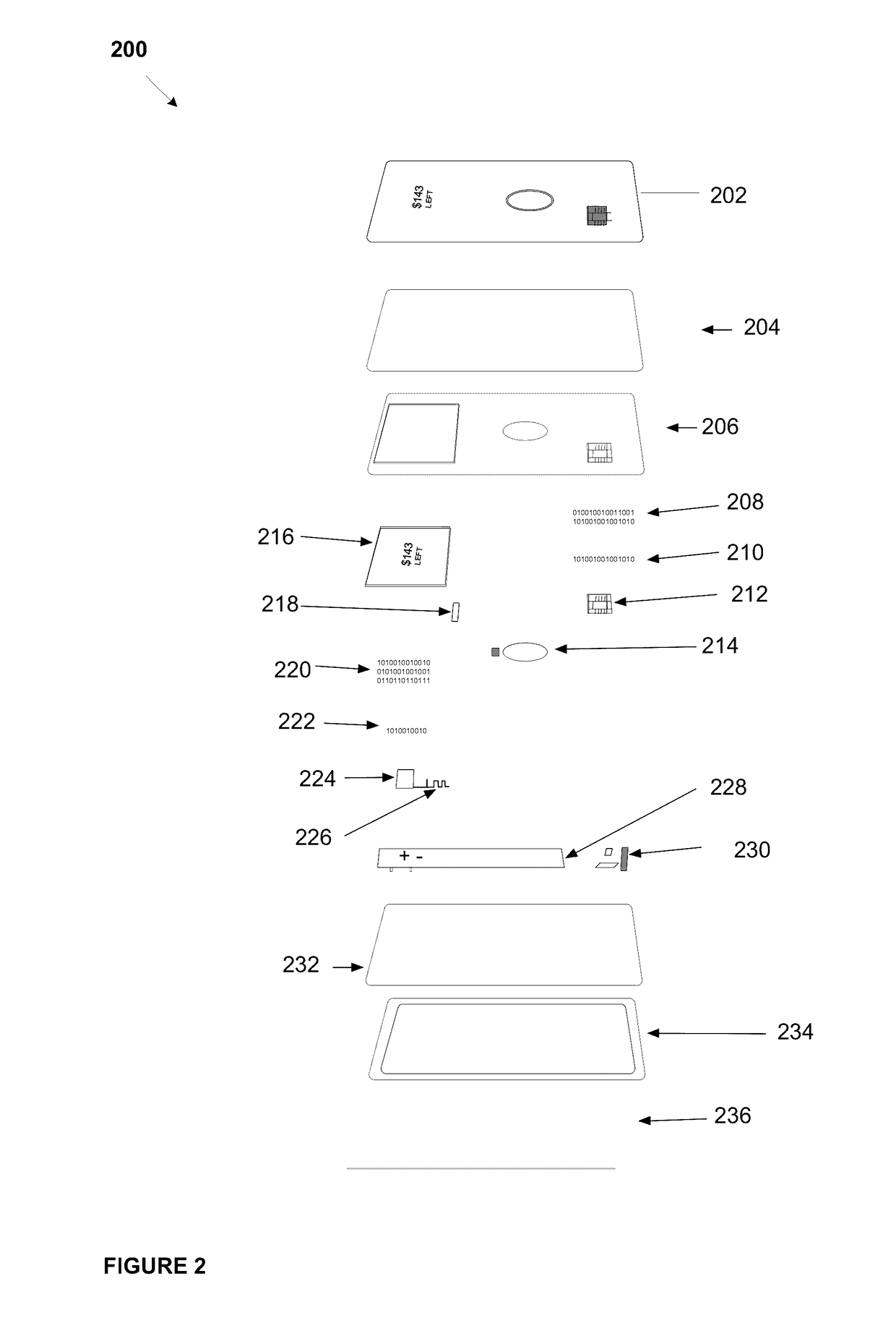
A dynamic transaction card that includes a transaction card having a number of layers, each of which may be interconnected to one another. For example, a dynamic transaction card may include an outer layer, a potting layer, a sensor layer that may detect and identify a card free fall and/or subsequent impact, which may trigger a microcontroller to send a mobile notification to a cardholder notifying the user that the card has been dropped, and/or may disable or deactivate the card and/or a user account associated with the card, a display layer (including, for example, LEDs, a dot matrix display, and the like), a microcontroller storing firmware, Java applets, Java applet integration, and the like, an EMV™ chip, an energy storage component, one or more antenna (e.g., Bluetooth™ antenna, NFC antenna, and the like), a power management component, a flexible printed circuit board (PCB), a chassis, and/or a card backing layer.

Description

CROSS REFERENCE TO RELATED APPLICATIONS[0001]The present application is a continuation-in-part of U.S. patent application Ser. No. 15 / 098,585, filed Apr. 14, 2016, which claims the benefit of U.S. Provisional Application No. 62 / 147,568 entitled “A System, Method, and Apparatus for a Dynamic Transaction Card” filed Apr. 14, 2015; and U.S. Provisional Application No. 62 / 270,669 entitled “A System, Method, and Apparatus for a Dynamic Transaction Card” filed Dec. 22, 2015. The entire contents of these applications are incorporated herein by reference.FIELD OF THE DISCLOSURE[0002]The present disclosure relates to a dynamic transaction card and the systems and methods relating to the dynamic transaction card. A dynamic transaction card may include components such as LEDs or light pipes embedded in the transaction card, an input mechanism, networking technologies, memory for storing transaction rules, transaction card preferences, applications, and / or a hearing and / or visual impairment inp...

Claims


Application Information

Patent Timeline
IPC IPC(8): G06Q20/34G08B5/22G06K19/07
CPCG06Q20/354G08B5/223G06K19/0724G06K19/0717G06K19/02G06K19/07707G06K19/07722G06K19/07733G06Q20/341G06Q20/352G06Q20/3552G06Q20/4016G06Q20/405
Inventor LOCKE, TYLERZARAKAS, JAMESWURMFELD, DAVIDKOEPPEL, ADAMKELLY, KEVIN
Owner CAPITAL ONE SERVICES
Why Eureka
Try Eureka