Wire harness

Inactive Publication Date: 2017-04-20
SUMITOMO WIRING SYST LTD
View PDF8 Cites 5 Cited by
  • Summary
  • Abstract
  • Description
  • Claims
  • Application Information

AI Technical Summary

Benefits of technology

[0013]With this configuration, the rear holder includes a rubber seal through-hole at one end of the slit, through which the middle tubular portion and the large-diameter tubular portion can pass. Therefore, the rubber seal can be attached to the coated electric wire before passing the coated electric wire through the slit in the rear holder. This does not mean that t

Problems solved by technology

Thereby, the waterproofing agent filling the spaces prevents the intru

Method used


Image

  • Wire harness
  • Wire harness
  • Wire harness

Examples


first embodiment

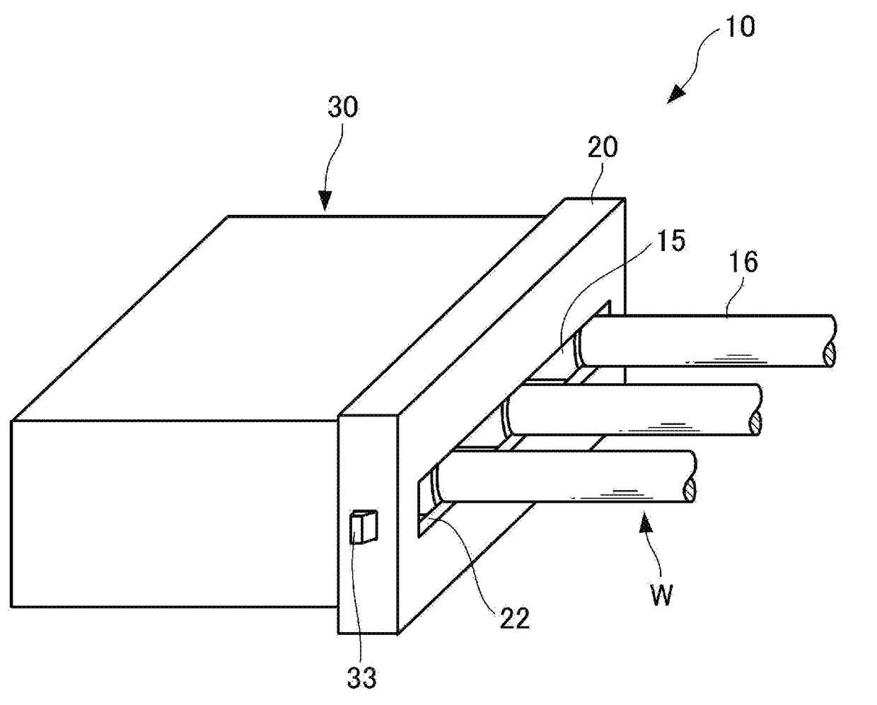
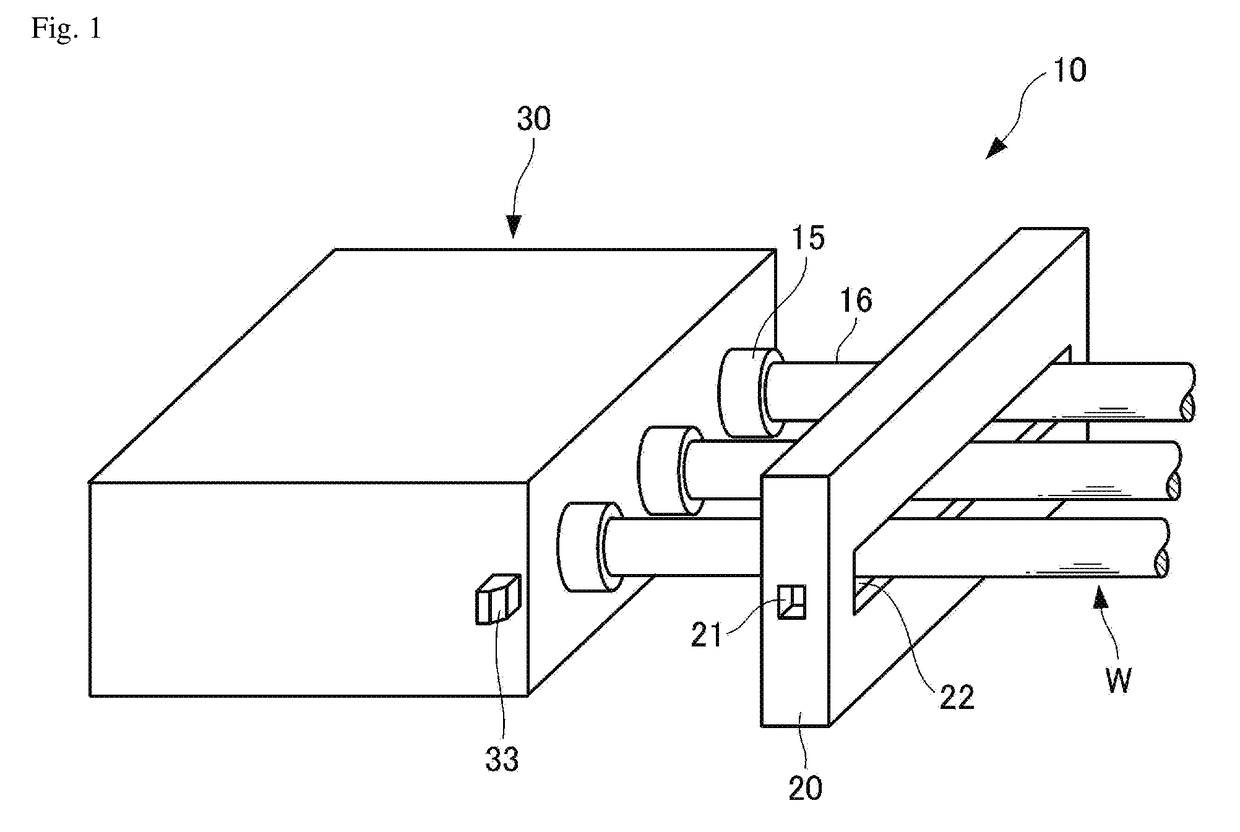
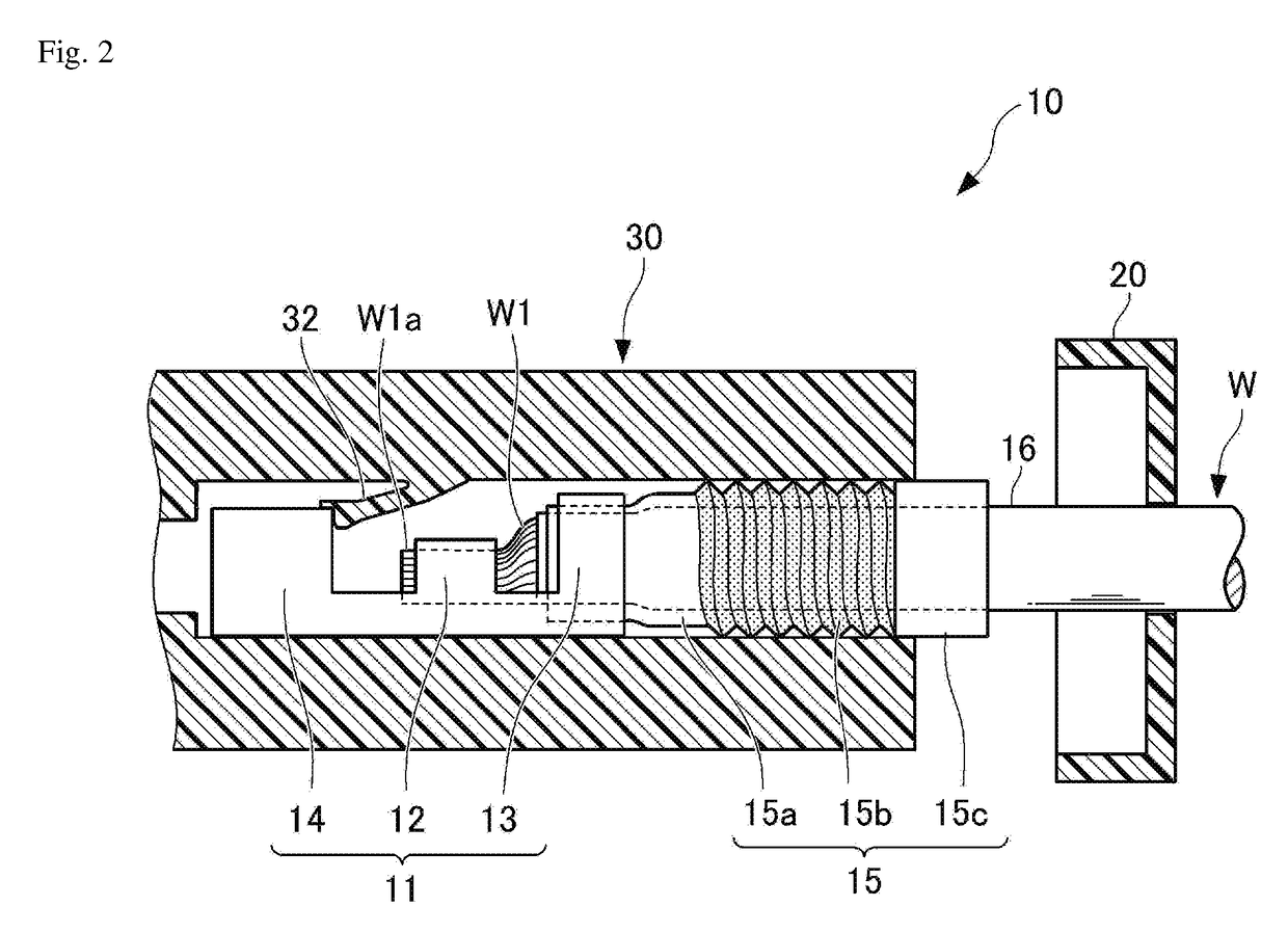
[0028]FIG. 1 illustrates a wire harness according to a first embodiment; FIG. 1 is a perspective view illustrating a state before a rear holder is attached to a connector. FIG. 2 is a cross-sectional view of an inside of the connector before the rear holder is attached to the connector.

[0029]As illustrated in FIG. 1, a wire harness 10 is provided with a plurality of coated electric wires W, a connector terminal 11, a connector 30, a rubber seal 15, and a rear holder 20.

[0030]As illustrated in FIG. 2, a coated electric wire W is covered with an insulation coating material 16 such as PVC, or the like. However, the insulation coating material 16 is stripped from the coated electric wire W beforehand from a portion of the coated electric wire W to be connected to the connector terminal 11. This exposes a conductor end portion W1a of a conductor W1, which is a bundle of small-diameter copper wires. More specifically, an end portion of the insulation coating material 16 is stripped off to...

second embodiment

[0051]FIGS. 6 and 7 illustrate a wire harness 10A according to a second embodiment of the present invention, before and after attaching a rear holder 20A, respectively. The only difference between the wire harness 10A and the wire harness 10 is that the rear holder 20 according to the first embodiment is different from the rear holder 20A. All other components are given the same reference numerals as in the first embodiment. A description of the configuration, function, and effects of the same components is omitted.

[0052]The rear holder 20A includes a slit 22 slightly wider than the diameter of the coated electric wire W and through which a plurality of coated electric wires W are inserted. Moreover, at one side of the slit 22 in the rear holder 20A a rubber seal through-hole 22a is provided through which the middle tubular portion 15b and the large-diameter tubular portion 15c of the rubber seal 15 can pass.

[0053]FIG. 8 is a front view illustrating the shape of the slit 22 in the r...


PUM


Abstract

A wire harness includes a plurality of coated electric wires; a connector terminal including a connection portion, a first barrel portion, and a second barrel portion; a connector configured to lock and store the connection portion; a rubber seal including a small-diameter tubular portion, a middle tubular portion having a spiral contour, and a large-diameter tubular portion, where the small-diameter tubular portion is secured by the second barrel portion along with an end portion of the insulation coating material. The middle tubular portion and the large-diameter tubular portion are force-fitted into a terminal insertion hole, and a rear holder is secured to the connector with the rubber seal pressed toward the terminal insertion hole, compressing the middle tubular portion axially. A waterproofing agent is applied to an outer surface of the middle tubular portion and is cured filling gaps between the middle tubular portion and the terminal insertion hole.

Description

CROSS-REFERENCE TO RELATED APPLICATIONS[0001]The present application claims priority under 35 U.S.C. §119 of Japanese Application No. 2015-206604, filed on Oct. 20, 2015, the disclosure of which is expressly incorporated by reference herein in its entirety.BACKGROUND OF THE INVENTION[0002]1. Field of the Invention[0003]The present invention relates to a wire harness, and specifically to a watertight wire harness used for connecting electric wires in vehicles and the like.[0004]2. Description of Related Art[0005]Conventionally, a connector housing accommodates electric wires in a connector. A rubber plug is placed over the electric wires at an entrance to the connector housing and the assembly is retained in a rear holder to make the connector housing more waterproof.[0006]The area around the rear holder and electric wire is filled with a sealant such as grease, or the like, to further improve the waterproofness of this kind of connector (see for instance, Japanese Patent Laid-open P...

Claims


Application Information

Patent Timeline
IPC IPC(8): H01B7/00H01R13/52H01R4/18H01R9/24H02G15/06H02G15/04
CPCH01B7/0045H02G15/06H01R13/521H01R4/185H01R9/2416H02G15/04H01R13/5208H01R2201/26H01R13/5205H01R13/5216H01R43/005
Inventor WAKABAYASHI, MASATAKAARAGIRI, SHOTA
Owner SUMITOMO WIRING SYST LTD
Why Eureka
Try Eureka