
Low dispersion gas-liquid separator

a gas-liquid separator and low-dispersion technology, applied in liquid degasification, separation processes, instruments, etc., can solve the problems of cross contamination, adverse dispersion, splattering, etc., to minimize cross contamination of solvents, minimize additional dispersion, and enhance separation of liquids

Active Publication Date: 2017-04-27
WATERS TECH CORP
View PDF20 Cites 4 Cited by
  • Summary
  • Abstract
  • Description
  • Claims
  • Application Information

AI Technical Summary

Benefits of technology

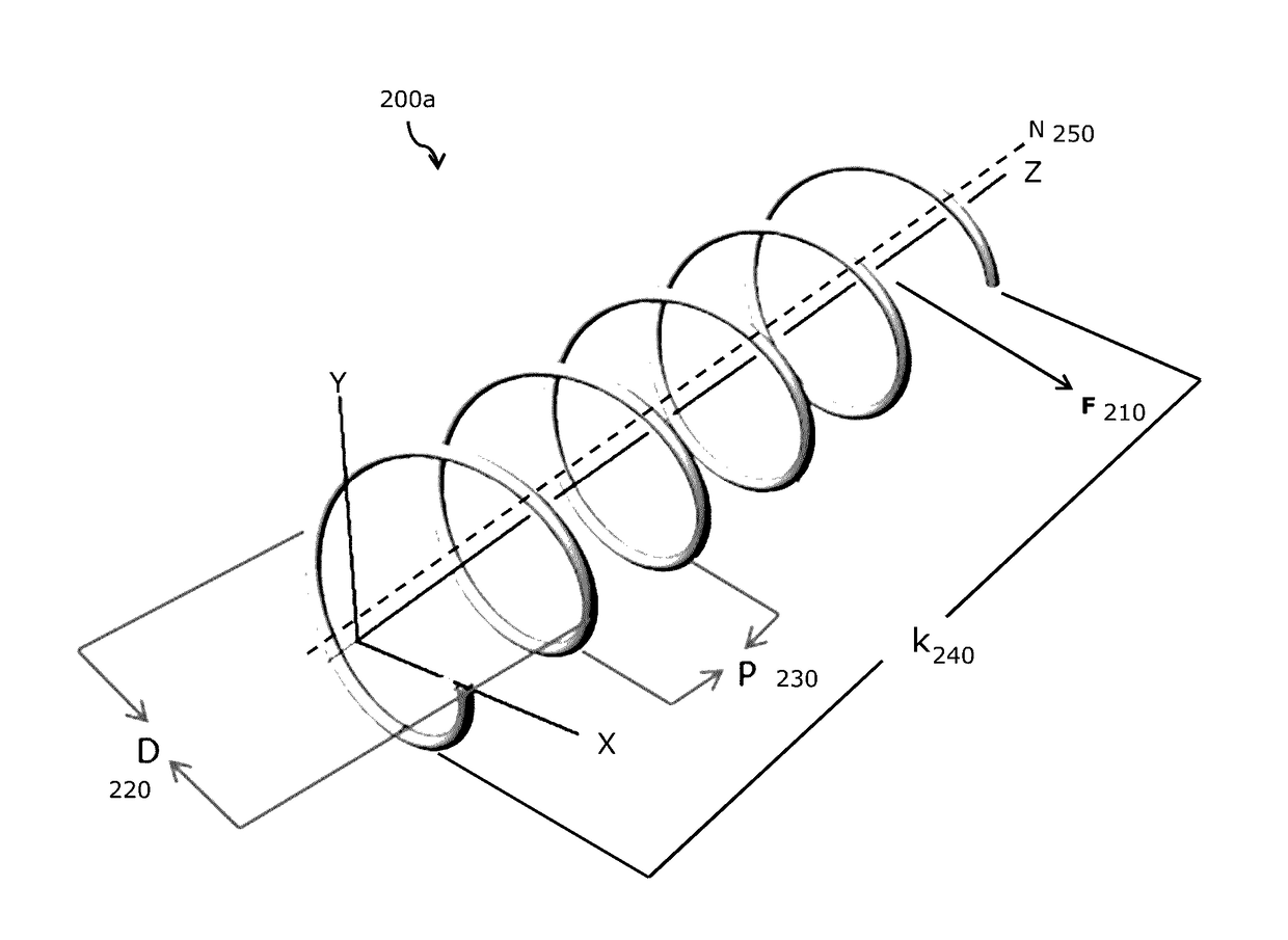
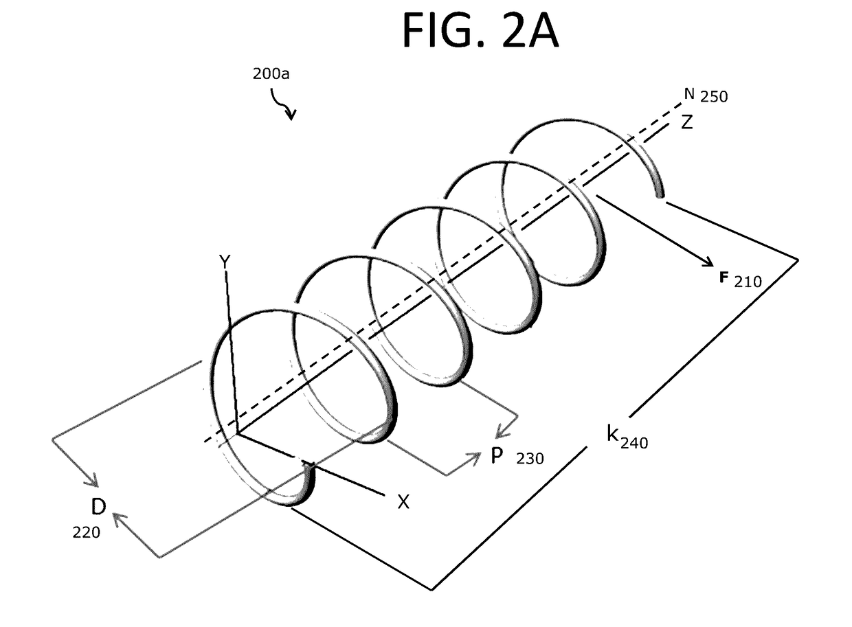
The present technology is a gas-liquid separator with a curved flow path that reduces dispersion, which is a problem in conventional separators. The narrow flow path creates a shift in the flow velocity, causing liquid to flow down the inner bend radius of the path and increasing the separation of gas and liquid. This results in more efficient collection and purer products. The technology also minimizes dispersion and cross-contamination, improves liquid / gas recovery, and allows for better separation of the phases. Overall, the invention provides better results and better efficiency in gas-liquid separations.

Problems solved by technology

The separating components, which collect in the vessel of conventional systems, can create splattering.
This splattering creates additional adverse dispersion and cross-contamination.

Method used


Image

  • Low dispersion gas-liquid separator
  • Low dispersion gas-liquid separator
  • Low dispersion gas-liquid separator

Examples


example 1

Food Coloring and Carbon Dioxide

[0100]An exemplary curvilinear flow path was prepared using transparent 0.250 inch id tubing. The curvilinear flow path included 3 loops and was similar to the embodiment 650 shown in FIG. 6. Fluids, including a multi-phase fluid, were flowed through the tubing to observe the flow pattern. The flow patterns were observed with the aid of liquid food coloring. In particular, a mixture of food coloring and carbon dioxide was flowed through the curvilinear flow path. It was observed that the food coloring, which is a liquid, collected or pooled on the inner bend radius.


PUM

PropertyMeasurementUnit
angleaaaaaaaaaa
angleaaaaaaaaaa
angleaaaaaaaaaa

Abstract

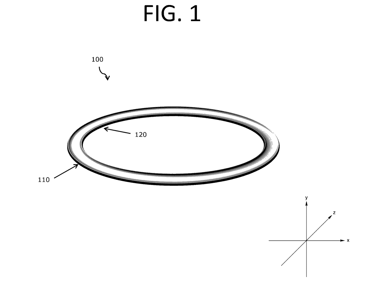
The present technology relates to methodologies, systems and apparatus for separating a liquid and a gas from a multi-phase flow stream. In particular, a gas-liquid separator having a curvilinear flow path sized is described. The flow path is designed to create a shift in the axial velocity of the primary flow field through the gas-liquid separator and generate a secondary flow field effect perpendicular to the primary flow field. The curvilinear flow path can minimize additional dispersion and provide improved efficiencies in fraction collection.

Description

RELATED APPLICATION[0001]This application claims the benefit of and priority to U.S. Provisional Application No. 62 / 246334, filed Oct. 26, 2015, and titled “Low Dispersion Gas-Liquid Separator,” which is owned by the assignee of the instant application and the disclosure of which is hereby incorporated by reference in its entirety.TECHNICAL FIELD[0002]The present technology relates to a gas-liquid separator for separating a liquid and a gas from a multi-phase flow stream. In particular, the present disclosure relates to methodologies, systems and apparatus for separating a liquid and a gas from a multi-phase flow stream within a gas-liquid separator. The gas-liquid separator can be used, for example, in carbon dioxide based chromatography preparative or analytical systems. In addition, the gas-liquid separator can be used in carbon dioxide based extraction systems.BACKGROUND OF THE TECHNOLOGY[0003]In general, chromatography involves the flowing of a mobile phase over a stationary ph...

Claims


Application Information

Patent Timeline
Patent Type & Authority Applications(United States)
IPC IPC(8): B01D45/04B01D53/02G01N30/02B01D45/12
CPCB01D45/04B01D45/12B01D2011/007G01N30/02B01D11/00B01D53/025B01D15/24B01D19/0052B01D15/40G01N30/84B01D19/00
Inventor BALA, SENTHILFREDETTE, COLINSEITH, CHRISTOPHER
Owner WATERS TECH CORP
Learn More