Eureka AIR delivers breakthrough ideas for toughest innovation challenges, trusted by R&D personnel around the world.

Human interface for vehicle automation

a human interface and vehicle technology, applied in the field of human computer interfaces, can solve the problems of reducing the display, revealing no means for dealing with physical controls, and reducing the display life, so as to maximize the display space and resist damage

Inactive Publication Date: 2017-04-27
PRYOR TIMOTHY R
View PDF3 Cites 12 Cited by
  • Summary
  • Abstract
  • Description
  • Claims
  • Application Information

AI Technical Summary

Benefits of technology

The patent describes a system where a screen and control surface can be constructed of material that can be sterilized and easily maintained in a healthcare setting. The system can automatically adjust its projection and sensing coordinates based on the location of fixed targets on the screen and control surface, allowing for accurate projection and sensing even when the surface is in a certain position. This makes it convenient for people in bed or other locations to hold the screen and control surface without physical connection to the projector and sensor unit, thereby reducing the risk of injury and ensuring safety. The system can also be used in beds in a home or hotel, providing useful information and amusement to patients while minimizing the need for wires or wireless transmission. Additionally, the patent describes a method of determining the position and orientation of the screen in free space using sensing functions built into the projector or a separate sensor.

Problems solved by technology

This device utilizes radiation from a large group of expensive UV LEDs to traverse the active display material which can cause degradation problems and warranty issues with such displays, in addition to adding considerable cost.
And it discloses no means for dealing with physical controls which may be used in conjunction with a display.

Method used


Image

  • Human interface for vehicle automation
  • Human interface for vehicle automation
  • Human interface for vehicle automation

Examples


Embodiment Construction

[0071]My application Ser. No. 12 / 748,666, of which this application is a continuation-in-part, discloses in FIG. 17 thereof a new form of easily sterilizable and cleanable control device for use in hospitals and nursing homes. The complete separation of the items contacted by persons from the operating electronics allows knobs and other physical controls and the touch screen to be easily cleaned or sterilized without harming the electronics or voiding the warranty thereof.

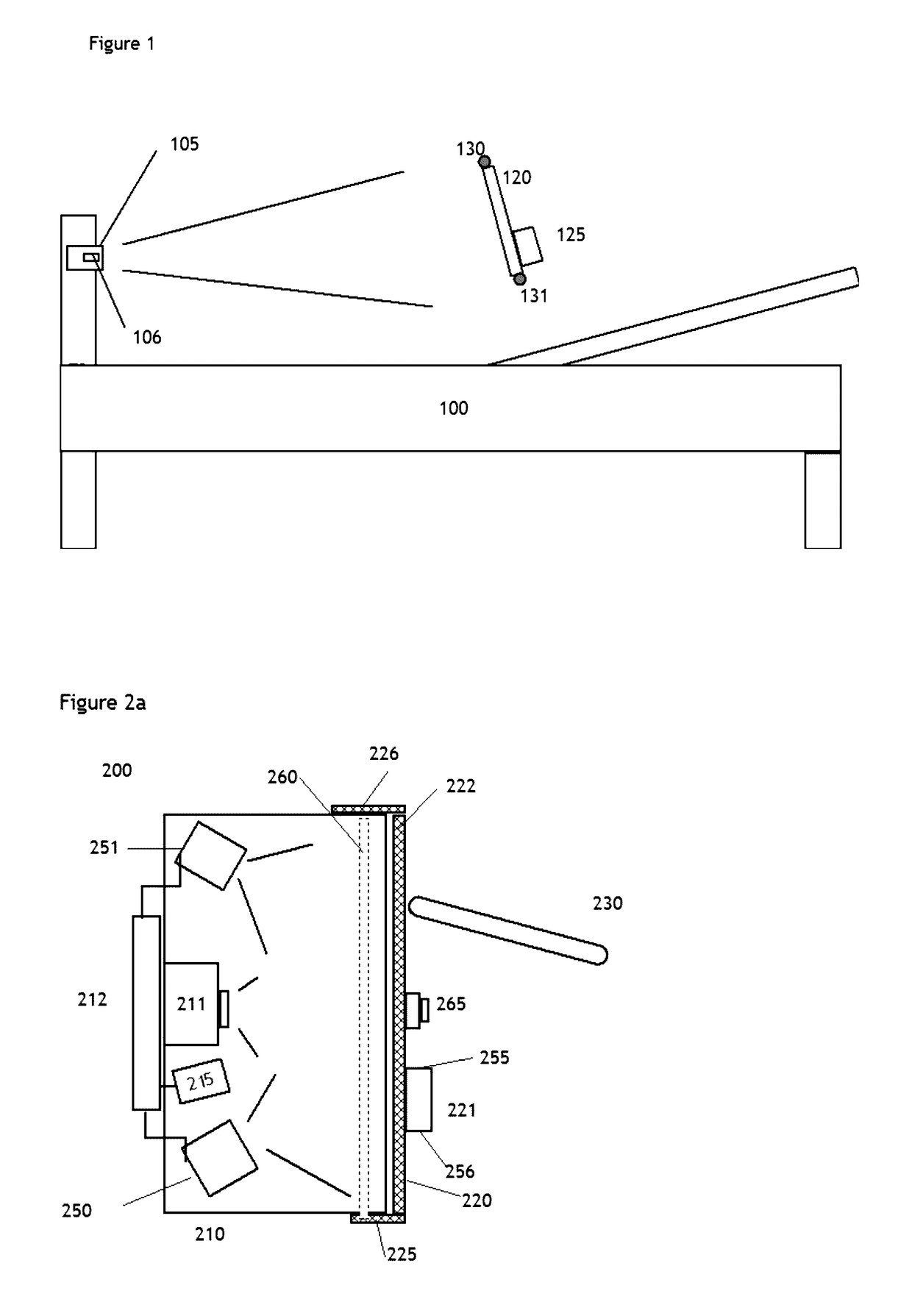
[0072]FIG. 1 illustrates a similar embodiment which makes use of the unique ability of the invention to have an easy to clean and even sterilize-able screen and control surface 120, in this case for use in a hospital bed 100. As shown the projector & sensor module 105 which includes camera 106 if a separate camera is required, is located at the foot of the bed, or alternatively in other locations such as the side of the bed, and illuminates and views the screen and control surface from the rear. A computer not show...


PUM


Abstract

The invention concerns a system by which intelligent land vehicle, transportation and highway data can be usefully presented to, and acted on by, a driver of a vehicle, providing a bridge between the vehicles of today, and the automated vehicles of tomorrow. Preferred embodiments utilize displayed sensor based imagery the driver interacts with by touch, gesture or other methods in order to confirm or reject alert signals provided by sensors and to confirm or understand the operation of sensory systems of the vehicle. The driver may designate data displayed for further processing by onboard computers, for example to track certain conditions. An advantageous result is that sensing systems can be set to a higher level of sensitivity and control and a data bank can be built up of sensed data and human responses which can be used over time to improve performance and safety of the vehicle.

Description

CROSS-REFERENCE TO RELATED APPLICATIONS[0001]The disclosures of the following patent applications are incorporated by reference in their entirety: U.S. provisional application 61 / 842,340, filed Jul. 2, 2013; U.S. patent application Ser. No. 12 / 748,666, filed Mar. 29, 2010; U.S. patent application Ser. No. 11 / 832,134, filed Aug. 1, 2007; U.S. provisional application 60 / 835,072, filed Aug. 3, 2006; U.S. patent application Ser. No. 11 / 349,350, filed Feb. 8, 2006; U.S. patent application Ser. No. 11 / 319,807 (now U.S. Pat. No. 7,671,851), filed Dec. 29, 2005; U.S. patent application Ser. No. 11 / 184,076 (now U.S. Pat. No. 7,466,843), filed Jul. 19, 2005; U.S. patent application Ser. No. 11 / 045,131, filed Jan. 31, 2005; U.S. patent application Ser. No. 10 / 934,762 (now U.S. Pat. No. 8,287,374), filed Sep. 7, 2004; PCT / US04 / 09701, filed Mar. 31, 2004; U.S. patent application Ser. No. 10 / 611,814 (now U.S. Pat. No. 7,489,303), filed Jul. 2, 2003; U.S. patent application Ser. No. 09 / 789,538 (no...

Claims


Application Information

Patent Timeline
Patent Type & Authority Applications(United States)
IPC IPC(8): G06F3/042H04N7/18B60K35/00G06T7/20G06F3/01B60R1/00H04N5/232G06K9/00
CPCG06F3/0425H04N5/23293H04N7/183G06K9/00791B60K2350/1052G06F3/011B60R1/00B60K35/00B60R2300/802G06T7/20A61L2202/14G06F3/042G06F3/03547G06F3/0308G06F3/04883A61L2/10G06F2203/04104G06F2203/04808H04N23/63B60K35/10B60K2360/146B60K35/22G06V20/56
Inventor PRYOR, TIMOTHY R.
Owner PRYOR TIMOTHY R
Why Eureka
Eureka Blog
Learn More