Carbon nanotube field effect transistor-based pulse generator

a technology of field effect transistors and pulse generators, which is applied in pulse generators, pulse techniques, solid-state devices, etc., can solve the problems of consuming relatively high amounts of energy, long time delay of edge-triggered pulse generators, and short response time, so as to eliminate short circuit power consumption, the effect of reducing the time delay of input and outpu

Active Publication Date: 2017-04-27
NINGBO UNIV
View PDF8 Cites 2 Cited by
  • Summary
  • Abstract
  • Description
  • Claims
  • Application Information

AI Technical Summary

Benefits of technology

[0013]When signal input end of the pulse generator is connected to the input signal, the signal generated at the first node which is connecting the drain of the fifth CNFET, the drain of the sixth CNFET, the gate of the seventh CNFET, the gate of the ninth CNFET, the gate of the twelfth CNFET, and the gate of the fourteenth CNFET is the inverted signal of the input signal. If the input signal is at the low level (which is 0), the inverted signal of the input signal is at the high level (which is 1), and the ninth CNFET, the thirteenth CNFET, and the fourteenth CNFET are in the on-state, meanwhile the seventh CNFET, the eighth CNFET, and the twelfth CNFET are cut off, and the second node connecting the source of the eighth CNFET and the drain of the ninth CNFET and the third node connecting the source of the thirteenth CNFET and the drain of the fourteenth CNFET are at the low level, thus the signal output end of the pulse generator outputs the low level. When the input signal is at the rising edge, due to a time delay effect of the first CNFET, the second CNFET, the third CNFET, the fourth CNFET, the fifth CNFET, and the sixth CNFET, the signal variation at the fourth node connecting the drain of the fifth CNFET, the drain of the sixth CNFET, the gate of the seventh CNFET, the gate of the ninth CNFET, the gate of the twelfth CNFET, and the gate of the fourteenth CNFET undergoes three gate delay. At the same time, the seventh CNFET and the twelfth CNFET undergo three gate delay and change from off-state to on-state, and the ninth CNFET and the fourteenth CNFET undergo three gate delay and change from on-state to off-state. The eighth CNFET is in the on-state, and the thirteenth CNFET is cut off. The fifth node connecting the drain of the seventh CNFET, the drain of the eighth CNFET, the gate of the tenth CNFET, and the gate of the eleventh CNFET is at the low level first then changed to be at the high level. Therefore, the signal output end of the pulse generator is at the low level then changed to be at the high level, and finally changed from the high level to the low level, thus forming a narrow signal.
[0014]If the input signal is at the high level, the seventh CNFET, the eighth CNFET, and the twelfth CNFET are in the on-state, and the ninth CNFET, the thirteenth CNFET, and the four

Problems solved by technology

The double-edge-triggered pulse generators have a long time delay, and

Method used


Image

  • Carbon nanotube field effect transistor-based pulse generator
  • Carbon nanotube field effect transistor-based pulse generator
  • Carbon nanotube field effect transistor-based pulse generator

Examples


example 1

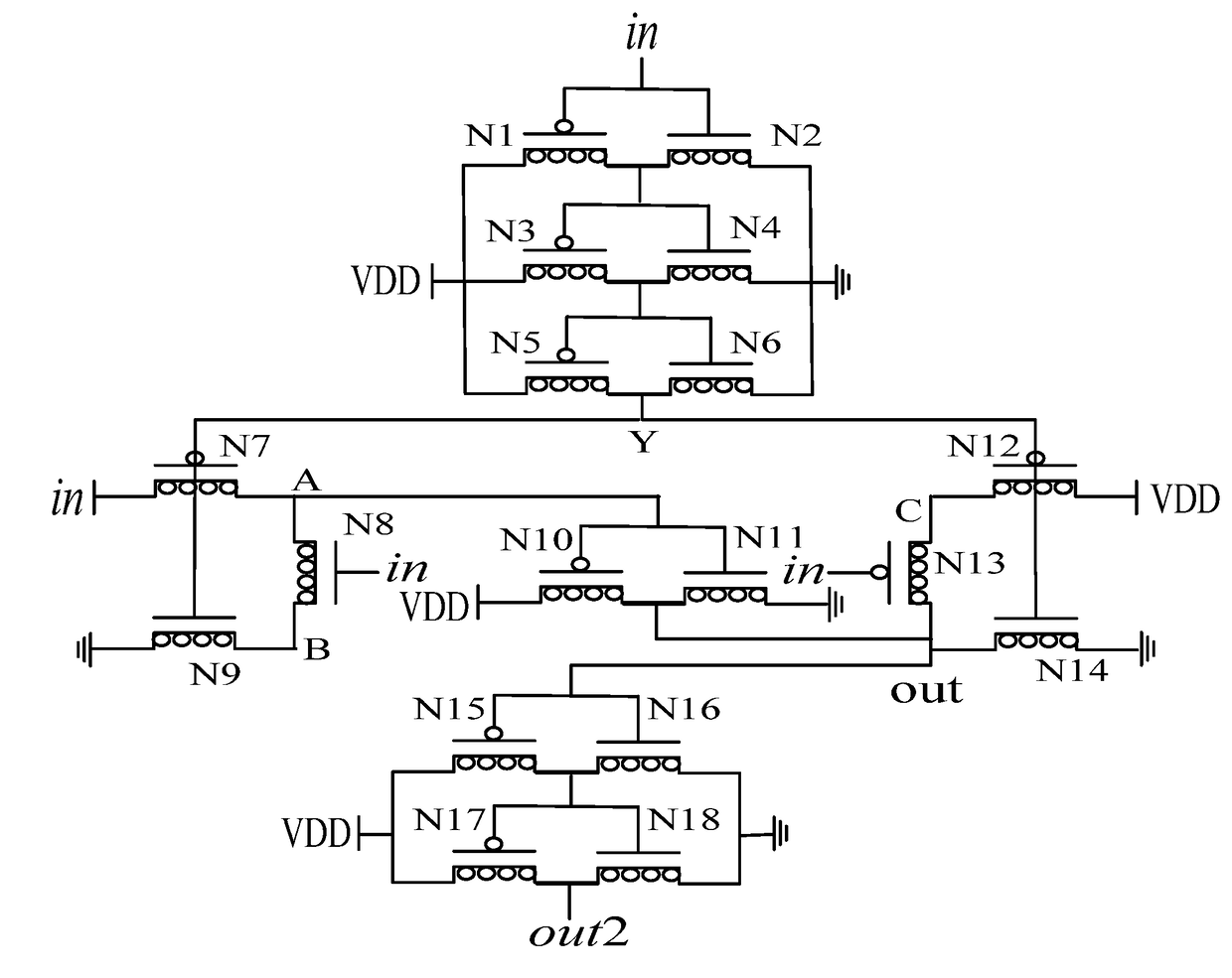
[0023]As shown in FIG. 3, a CNFET based pulse generator, comprising a first Carbon Nanotube Field Effect Transistor (CNFET) N1, a second CNFET N2, a third CNFET N3, a fourth CNFET N4, a fifth CNFET N5, a sixth CNFET N6, a seventh CNFET N7, an eighth CNFET N8, a ninth CNFET N9, a tenth CNFET N10, an eleventh CNFET N11, a twelfth CNFET N12, a thirteenth CNFET N13, and a fourteenth CNFET N14. The first CNFET N1, the third CNFET N3, the fifth CNFET N5, the seventh CNFET N7, the tenth CNFET N10, the twelfth CNFET N12, and the thirteenth CNFET N13 are P-type CNFET. The second CNFET N2, the fourth CNFET N4, the sixth CNFET N6, the eighth CNFET N8, the ninth CNFET N9, the eleventh CNFET N11, and the fourteenth CNFET N14 are N-type CNFET.

[0024]A gate of the first CNFET N1, a gate of the second CNFET N2, a source of the seventh CNFET N7, a gate of the eighth CNFET N8, and a gate of the thirteenth CNFET N13 are connected together, and a connection end thereof is a signal input end of the pulse...

example 2

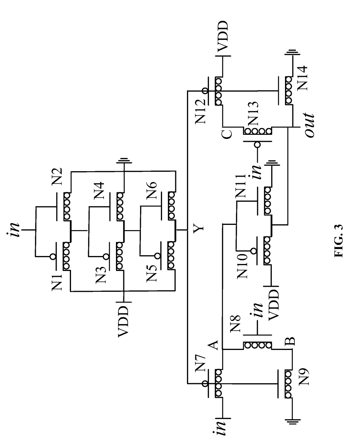
[0032]As shown in FIG. 3, a CNFET based pulse generator, comprising a first Carbon Nanotube Field Effect Transistor (CNFET) N1, a second CNFET N2, a third CNFET N3, a fourth CNFET N4, a fifth CNFET N5, a sixth CNFET N6, a seventh CNFET N7, an eighth CNFET N8, a ninth CNFET N9, a tenth CNFET N10, an eleventh CNFET N11, a twelfth CNFET N12, a thirteenth CNFET N13, and a fourteenth CNFET N14. The first CNFET N1, the third CNFET N3, the fifth CNFET N5, the seventh CNFET N7, the tenth CNFET N10, the twelfth CNFET N12, and the thirteenth CNFET N13 are P-type CNFET. The second CNFET N2, the fourth CNFET N4, the sixth CNFET N6, the eighth CNFET N8, the ninth CNFET N9, the eleventh CNFET N11, and the fourteenth CNFET N14 are N-type CNFET.

[0033]A gate of the first CNFET N1, a gate of the second CNFET N2, a source of the seventh CNFET N7, a gate of the eighth CNFET N8, and a gate of the thirteenth CNFET N13 are connected together, and a connection end thereof is a signal input end of the pulse...

example 3

[0035]As shown in FIG. 4, a CNFET based pulse generator, comprising a first Carbon Nanotube Field Effect Transistor (CNFET) N1, a second CNFET N2, a third CNFET N3, a fourth CNFET N4, a fifth CNFET N5, a sixth CNFET N6, a seventh CNFET N7, an eighth CNFET N8, a ninth CNFET N9, a tenth CNFET N10, an eleventh CNFET N11, a twelfth CNFET N12, a thirteenth CNFET N13, and a fourteenth CNFET N14. The first CNFET N1, the third CNFET N3, the fifth CNFET N5, the seventh CNFET N7, the tenth CNFET N10, the twelfth CNFET N12, and the thirteenth CNFET N13 are P-type CNFET. The second CNFET N2, the fourth CNFET N4, the sixth CNFET N6, the eighth CNFET N8, the ninth CNFET N9, the eleventh CNFET N11, and the fourteenth CNFET N14 are N-type CNFET.

[0036]A gate of the first CNFET N1, a gate of the second CNFET N2, a source of the seventh CNFET N7, a gate of the eighth CNFET N8, and a gate of the thirteenth CNFET N13 are connected together, and a connection end thereof is a signal input end of the pulse...


PUM


Abstract

A CNFET based pulse generator, including a first Carbon Nanotube Field Effect Transistor (CNFET), a second CNFET, a third CNFET, a fourth CNFET, a fifth CNFET, a sixth CNFET, a seventh CNFET, an eighth CNFET, a ninth CNFET, a tenth CNFET, an eleventh CNFET, a twelfth CNFET, a thirteenth CNFET, and a fourteenth CNFET. The first CNFET, the third CNFET, the fifth CNFET, the seventh CNFET, the tenth CNFET, the twelfth CNFET, and the thirteenth CNFET are P-type CNFETs. The second CNFET, the fourth CNFET, the sixth CNFET, the eighth CNFET, the ninth CNFET, the eleventh CNFET, and the fourteenth CNFET are N-type CNFETs.

Description

CROSS-REFERENCE TO RELATED APPLICATIONS[0001]Pursuant to 35 U.S.C. §119 and the Paris Convention Treaty, this application claims the foreign priority benefit of Chinese Patent Application No. 201510701869.3 filed Oct. 26, 2015, the contents of which, are incorporated herein by reference. Inquiries from the public to applicants or assignees concerning this document or the related applications should be directed to: Matthias Scholl P.C., Attn.: Dr. Matthias Scholl Esq., 245 First Street, 18th Floor, and Cambridge, Mass. 02142.BACKGROUND OF THE INVENTION[0002]Field of the Invention[0003]The invention relates to a pulse generator, and more particularly to a Carbon Nanotube Field Effect Transistor-based (CNFET-based) double-edge-triggered pulse generator.[0004]Description of the Related Art[0005]FIGS. 1-2 illustrate circuit diagrams of typical double-edge-triggered pulse generators. The double-edge-triggered pulse generators have a long time delay, and slow response speed. They also cons...

Claims


Application Information

Patent Timeline
IPC IPC(8): H03K3/012H03K3/037H01L27/28H01L51/00H01L51/05
CPCH03K3/012H01L51/0048H03K3/037H01L27/283H01L51/0566H03K3/356104H10K19/10H10K85/221H10K10/488
Inventor WANG, PENGJUNWANG, QIANGONG, DAOHUI
Owner NINGBO UNIV
Why Eureka
Try Eureka