Eureka AIR delivers breakthrough ideas for toughest innovation challenges, trusted by R&D personnel around the world.

Additive manufacturing part identification method and part

Inactive Publication Date: 2017-05-04
BAKER HUGHES INC
View PDF0 Cites 16 Cited by
  • Summary
  • Abstract
  • Description
  • Claims
  • Application Information

AI Technical Summary

Benefits of technology

This patent is about a method for making a part by adding material to a previously existing part. The part has two different materials that form a mark. The mark serves as a visual identifier of the part. This method can be useful for manufacturing parts that have specific properties and distinguishing them from other parts.

Problems solved by technology

This means that there is a potential risk for surface marks to be removed either intentionally or naturally through shipping interactions or use of the product.
Once the mark is gone, it is not often possible to easily discern whether the product is genuine or a fake without specific interrogation of the product.

Method used


Image

  • Additive manufacturing part identification method and part
  • Additive manufacturing part identification method and part
  • Additive manufacturing part identification method and part

Examples


embodiment 1

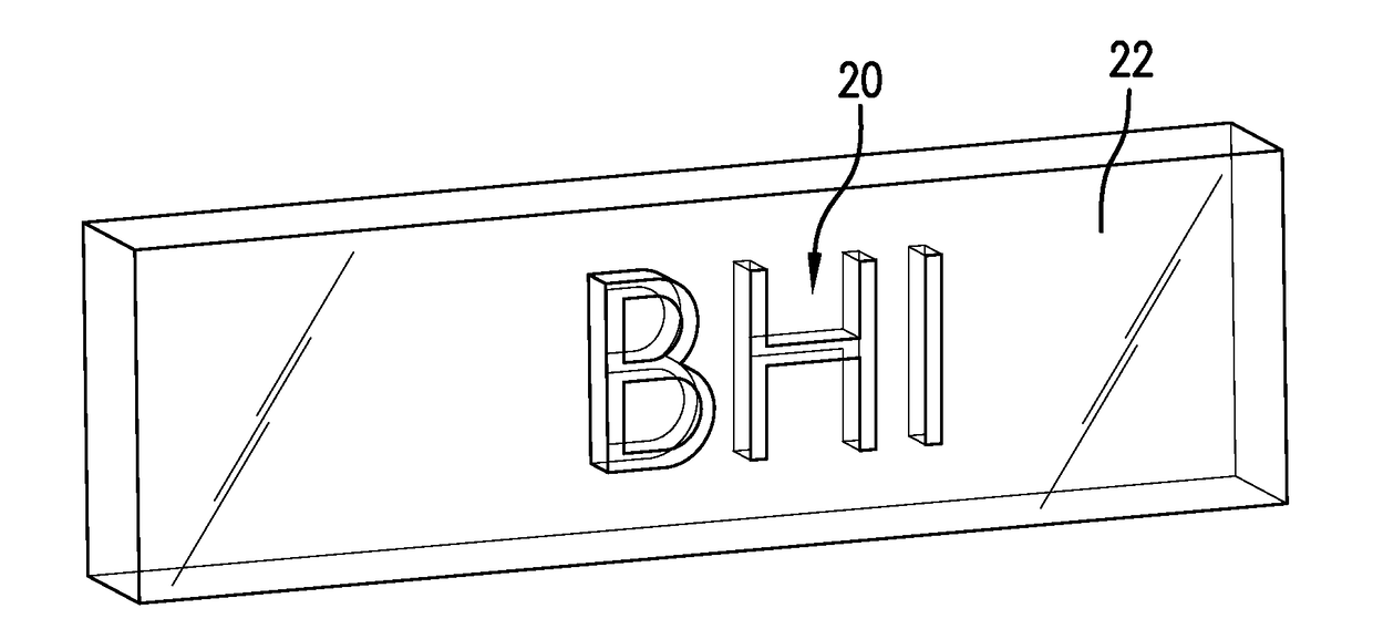
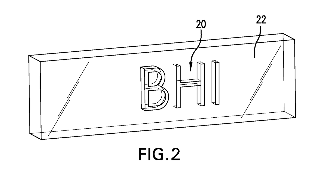
[0021]A part comprising: a material of the part having a first material property; a second material property of the first material or a different material, one of the first material property or the second material property being arranged to form a mark.

embodiment 2

[0022]The part of embodiment 1 wherein the one of the first material property or the second material property being arranged to form a mark is within the material of the other of the first material property and second material property

embodiment 3

[0023]The part of embodiment 1 wherein the material is metal, plastic or ceramic.


PUM

PropertyMeasurementUnit
Electrical conductivityaaaaaaaaaa
Poweraaaaaaaaaa
Densityaaaaaaaaaa

Abstract

A part including a material of the part having a first material property. A second material property of the first material or a different material, one of the first material property or the second material property being arranged to form a mark. A method for producing a part.

Description

BACKGROUND[0001]Oftentimes it is of value to manufacturers to mark their own products in ways that might be difficult to reproduce so that counterfeit products may be more easily identified through the absence of the correct indicia. Various marking methods have been used over the centuries, usually on the surface of the particular product, using paint, stain, stamps, etching (e.g. mechanical or laser), sand blasting using a mask, etc. Each of these has been used with various degrees of success in connection with both durability of the mark and thwarting a prospective counterfeiter.[0002]Marking being what it is, the arts employing the same have been limited to the surface of the part for most marking other than producing product in a certain color or the like. This means that there is a potential risk for surface marks to be removed either intentionally or naturally through shipping interactions or use of the product. Once the mark is gone, it is not often possible to easily discer...

Claims


Application Information

Patent Timeline
IPC IPC(8): B22F3/24G09F3/00B29C67/00B29C71/00B22F7/02B22F3/105
CPCB22F3/24B33Y70/00B22F3/1055B29C67/0081B29C71/00G09F3/00B33Y10/00B33Y80/00B29K2071/00B29K2105/16B29K2995/0008B29K2995/0005B29K2995/0013B29K2995/0064B22F7/02B29C64/165B22F7/06B22F2999/00C22C2202/02B23K26/342B29C64/393B29C64/10B23K2103/00B23K2103/42B23K2103/52Y02P10/25B22F10/38B22F10/36B22F10/28B22F10/25B22F2207/17
Inventor GOEING, FREDERIKWANGENHEIM, CHRISTOPHMICHAELIS, GUNNAR
Owner BAKER HUGHES INC
Why Eureka
Eureka Blog
Learn More