
System and method of performing scanning probe microscopy on a substrate surface

a scanning probe and substrate surface technology, applied in the direction of instruments, measurement devices, nanotechnology, etc., can solve the problems of loss of accuracy and the limited scope of the scanning probe device, and achieve the effect of improving accuracy

Active Publication Date: 2017-05-11
NEDERLANDSE ORG VOOR TOEGEPAST-NATUURWETENSCHAPPELIJK ONDERZOEK (TNO)
View PDF6 Cites 5 Cited by
  • Summary
  • Abstract
  • Description
  • Claims
  • Application Information

AI Technical Summary

Benefits of technology

The invention provides a way to do scanning probe microscopy that works well on large surfaces without sacrificing accuracy.

Problems solved by technology

A disadvantage, for example, is that SPM devices are usually limited to inspection of relatively small substrate surfaces.
A larger positioning loop means more compliance in actuated parts and loss of accuracy.

Method used


Image

  • System and method of performing scanning probe microscopy on a substrate surface
  • System and method of performing scanning probe microscopy on a substrate surface
  • System and method of performing scanning probe microscopy on a substrate surface

Examples


Embodiment Construction

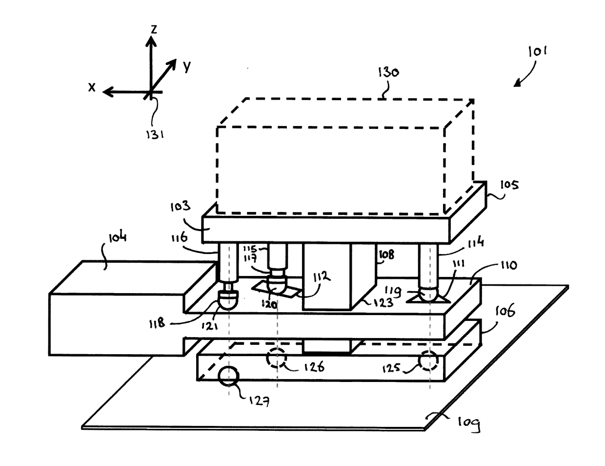
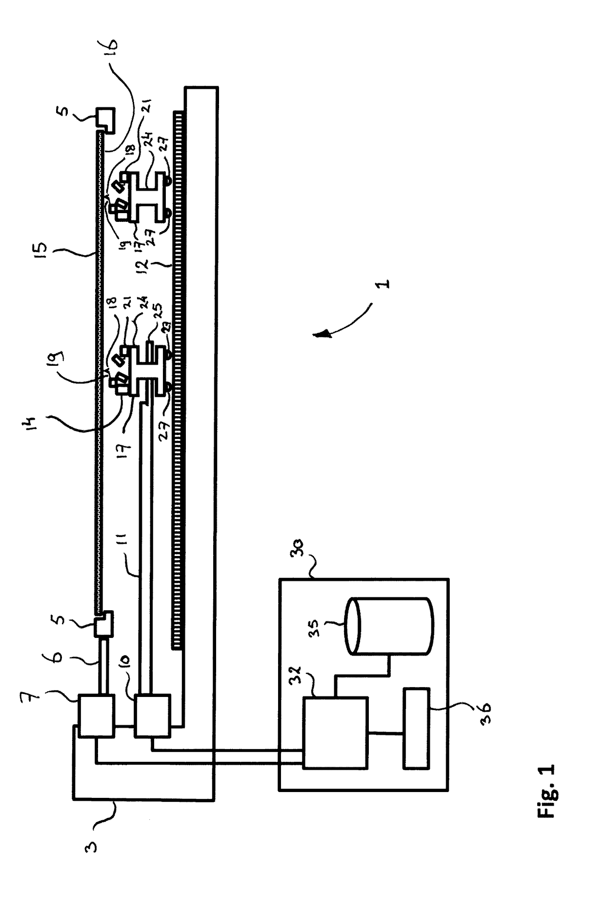
[0030]FIG. 1 schematically illustrates a scanning probe microscopy (SPM) system 1 of the present invention. The SPM system 1 is suitable for being used in combination with the method of performing scanning probe microscopy in accordance with the present invention. The SPM system 1 comprises a metrology frame 3. The metrology frame provides a solid fixed base for the system. For obtaining the desired accuracy, the metrology frame is preferably kept free from any vibrations, and ideally also temperature changes within or in the environment of the metrology frame 3 are ruled out as much as possible.

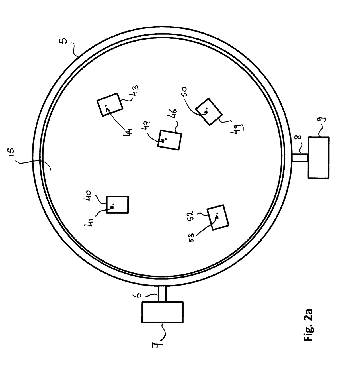
[0031]A substrate holder 5 for carrying a substrate 15 such as a wafer, is connected to an XY substrate holder actuator 7 by means of a substrate holder arm 6.

[0032]The substrate holder actuator 7 may be a system that allows to move the substrate holder 5, and therewith the substrate 15, in the X and Y directions, i.e. the directions parallel to the substrate 15. In FIG. 1, the substrate hol...


PUM


Abstract

The invention is directed at a method of performing scanning probe microscopy on a substrate surface using a scanning probe microscopy system, the system including at least one probe head, the probe head comprising a probe tip arranged on a cantilever and a tip position detector for determining a position of the probe tip along a z-direction transverse to an image plane, the method comprising: positioning the at least one probe head relative to the substrate surface; moving the probe tip and the substrate surface relative to each other in one or more directions parallel to the image plane for scanning of the substrate surface with the probe tip; and determining the position of the probe tip with the tip position detector during said scanning for mapping nanostructures on the substrate surface; wherein said step of positioning is performed by placing the at least one probe head on a static carrier surface.

Description

FIELD OF THE INVENTION[0001]The present invention is directed at a method of performing scanning probe microscopy on a substrate surface using a scanning probe microscopy system, the system including at least one probe head, the probe head comprising a probe tip arranged on a cantilever and a tip position detector for determining a position of the probe tip along a z-direction transverse to an image plane, the method comprising positioning the at least one probe head relative to the substrate surface.[0002]The invention is further directed at a scanning probe microscopy system for performing microscopy on a substrate surface, the system including at least one probe head, the probe head comprising a probe tip arranged on a cantilever and a tip position detector for determining a position of the probe tip along a z-direction transverse to an image plane, wherein the system comprises a positioning structure for positioning the at least one probe head relative to the substrate surface.B...

Claims


Application Information

Patent Timeline
IPC IPC(8): G01Q10/04G01Q70/02
CPCG01Q70/02G01Q10/04G01Q10/06G01Q70/06B82Y35/00
Inventor SADEGHIAN MARNANI, HAMEDWINTERS, JASPERCROWCOMBE, WILLIAM EDWARDVAN DEN DOOL, TEUNIS CORNELISKRAMER, GEERTEN FRANS LJSBRAND
Owner NEDERLANDSE ORG VOOR TOEGEPAST-NATUURWETENSCHAPPELIJK ONDERZOEK (TNO)
Learn More