Focal-plane shutter and optical apparatus
- Summary
- Abstract
- Description
- Claims
- Application Information
AI Technical Summary
Benefits of technology
Problems solved by technology
Method used
Image

Examples
Embodiment Construction
[0039]An embodiment of the invention will be described below with reference to the drawings.
(Optical Apparatus)
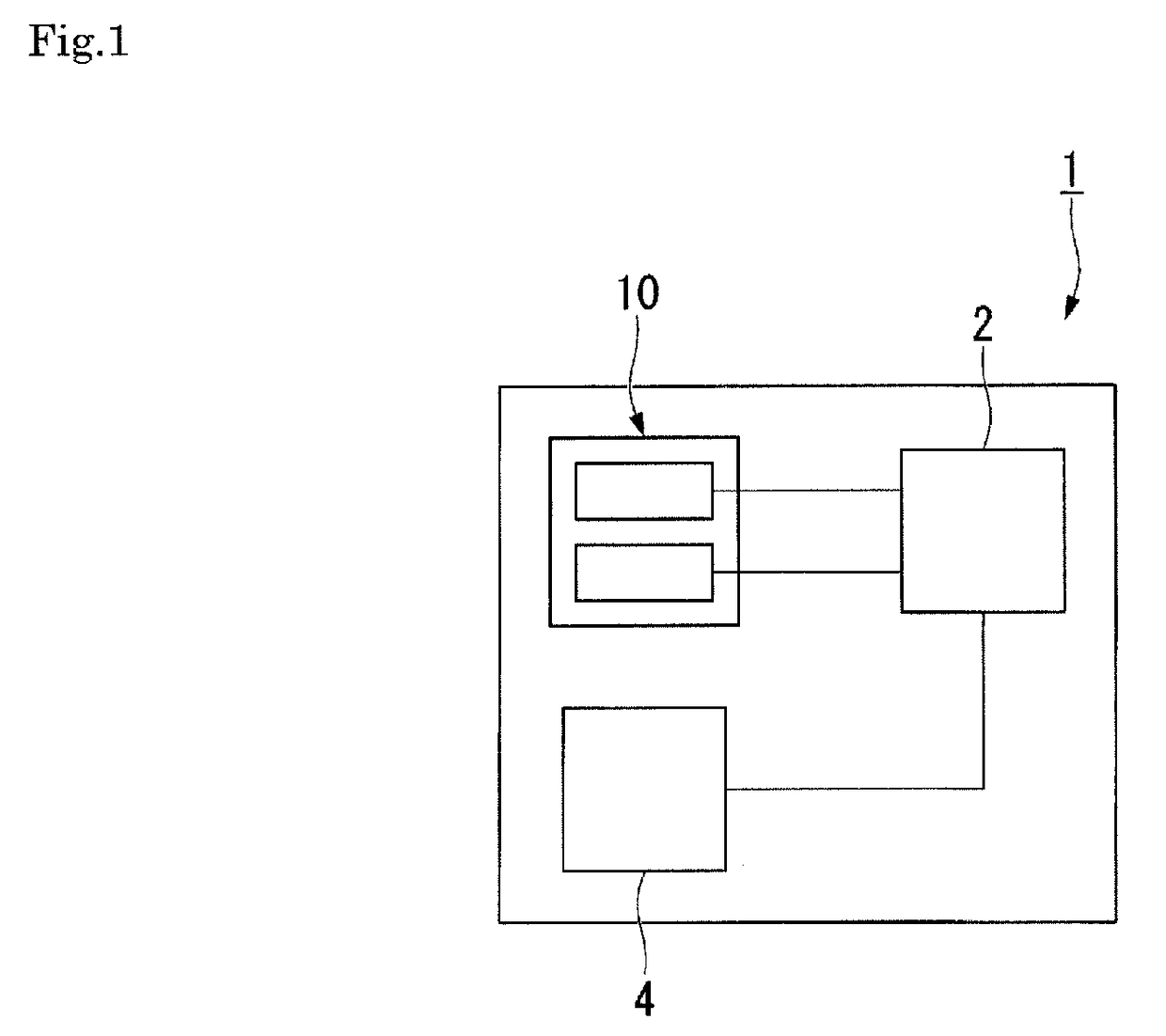
[0040]FIG. 1 is a block diagram of an optical apparatus.
[0041]An optical apparatus 1 is, for example, a digital camera or a still camera and includes a controller 2, an imaging device 4, and a focal-plane shutter 10, as shown in FIG. 1.
[0042]The controller 2 controls the overall action of the optical apparatus 1 and includes a CPU (central processing unit), a ROM (read only memory), a RAM (random access memory), and other components. The controller 2 controls the action of the focal-plane shutter 10, which will be described later.
[0043]The imaging device 4 is, for example, a CCD (charge coupled device) or a CMOS (complementary metal oxide semiconductor) image sensor and converts a subject image formed by light into an electric signal.
[0044]The optical apparatus 1 further includes, although not shown in FIG. 1, a lens and other components for focal length adjustment.
(Focal-P...
PUM
 Abstract
Description
Claims
Application Information