Breathing system and seat for aircraft crew member or passenger

a technology for aircraft crew members and seats, which is applied in the field of breathing systems and seats for aircraft crew members or passengers, can solve the problems of cumbersome support and consumption of oxygen-containing gas, and achieve the effect of convenient operation

a technology for aircraft crew members and seats, which is applied in the field of breathing systems and seats for aircraft crew members or passengers, can solve the problems of cumbersome support and consumption of oxygen-containing gas, and achieve the effect of convenient operation

US20170136269A1Active Publication Date: 2017-05-18SAFRAN AEROTECHNICS

Image

  • Breathing system and seat for aircraft crew member or passenger
  • Breathing system and seat for aircraft crew member or passenger
  • Breathing system and seat for aircraft crew member or passenger

Examples


Embodiment Construction

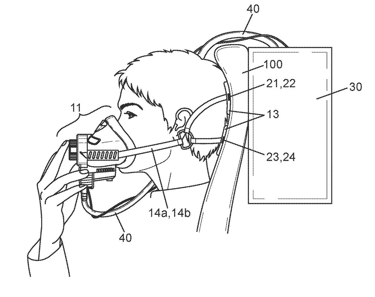
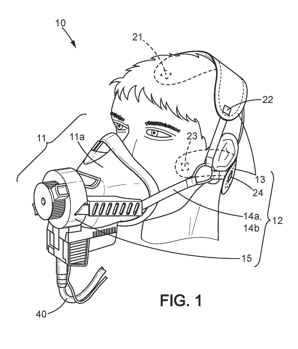
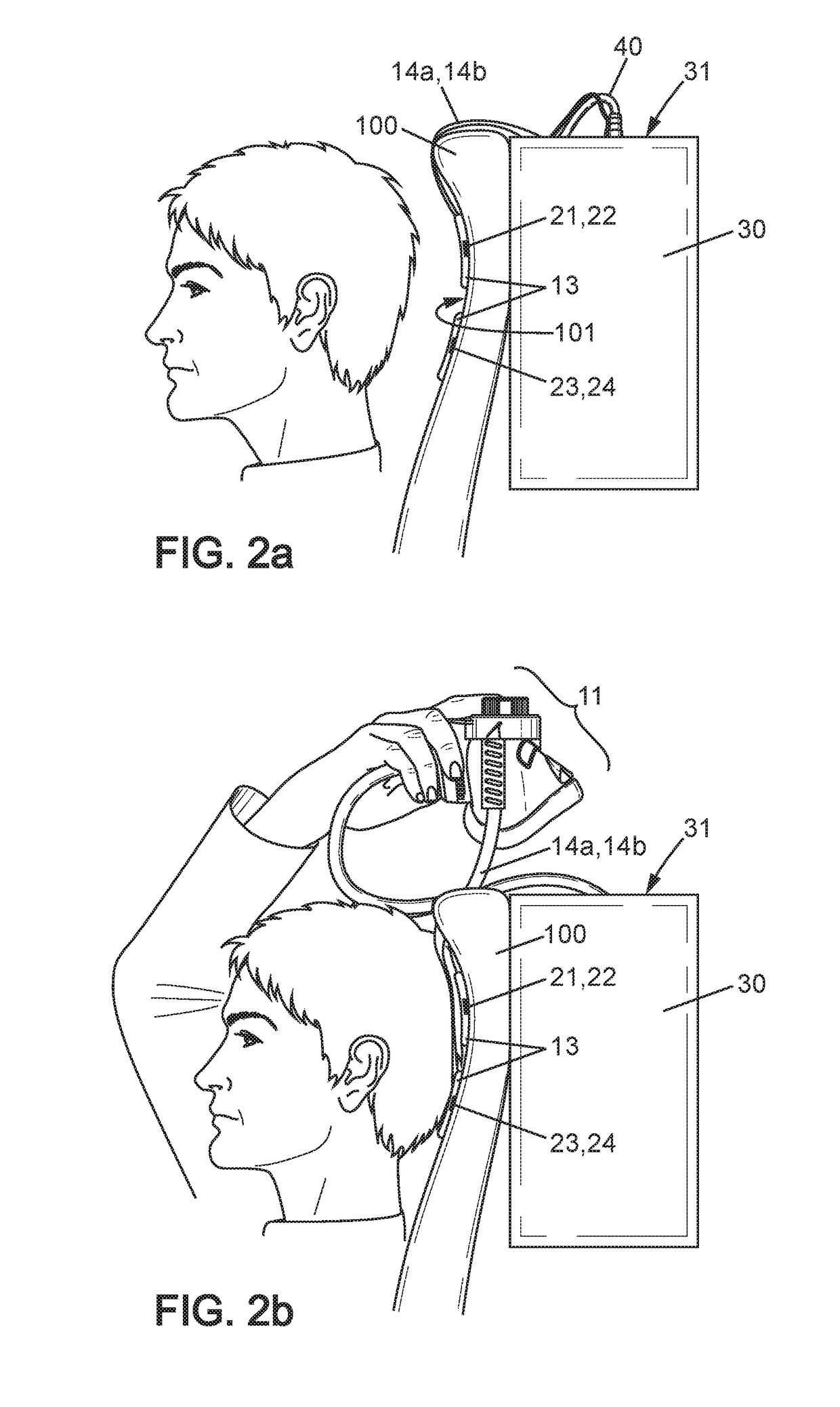
[0047]A breathing system according to the invention comprises an end-user part 10, an oxygen source unit (not shown), storage means and a removable fixing means 21-24. It is intended to be used in case of depressurization of the aircraft or in case of emergency, for example when smoke develops within the aircraft.

[0048]The end-user part 10 is intended to be put on the head by an aircraft crew member, and then delivers an oxygen-containing gas to breath-in by the crew member instead of breathing ambient air. The end-user part 10 is comprised of a face-fitting device 11 to be placed in front of the nose and mouth of the crew member, and holding means 12 which retain the face-fitting device 11 on the crew member's face after the end-user part 10 has been put on by the crew member. The holding means 12 comprise a back portion 13 which applies onto the top or back part of the head in put-on position, for retaining the face-fitting device 11. In alternative embodiments of the invention, t...


PUM


Abstract

A breathing system for an aircraft crew member or passenger comprises a face-fitting device (11), storage means added to a seat headrest (100) for retaining the face-fitting device in a storage position apart from the head, and a back portion (13) for retaining the face-fitting device on the user's head when the breathing system is used. The back portion is retained on the headrest by removable fixing means (21-24) when the face-fitting device is in the storage position, and said removable fixing means are released upon tightening the face-fitting device on the user's head.

Description

[0001]The invention relates to a breathing system and a seat for an aircraft crew member or passenger.BACKGROUND OF THE INVENTION[0002]In an aircraft such as a plane, the pilots, crew members or passengers are each provided with a breathing system capable of delivering oxygen to a face-fitting device. In case of depressurization or urgency, the user should be able to catch the face-fitting device from the storage position of this latter and place it correctly onto his face for breathing within this face-fitting device. Depending on the aircraft type and also special requirements or standards, the face-fitting device may cover only the nose and mouth of the user, or may be combined with a mask so as to cover the whole face. Major constraints to be met by the breathing systems implemented relate to the time necessary for the user to catch the face-fitting device and place it onto his face, and also with the weight and reliability of the breathing system.[0003]Additional constraints re...

Claims


Application Information

Patent Timeline
18 May 2017
Publication
US20170136269A1
IPC
A62B18/08; A62B18/02; A62B25/00; B64D11/00
CPC
A62B18/084; B64D11/00; B64D2231/025; A62B25/005; A62B18/025; A62B7/14
Inventors
JACOTEY, JEREMY; LEMASSON, DOMINIQUE