Magnetically Connected Block

a technology of magnetic connections and blocks, applied in toys, entertainment, etc., can solve the problems of limiting the diversity and interest of stacking electronic blocks, serious electricity consumption, etc., and achieve the effects of reducing manufacturing costs, facilitating user observation of operating state, and being easy to be affected

Inactive Publication Date: 2017-05-18
SHENZHENSHI HANTONG TECH CO LTD
View PDF24 Cites 2 Cited by
  • Summary
  • Abstract
  • Description
  • Claims
  • Application Information

AI Technical Summary

Benefits of technology

[0015]In some embodiments, the magnetically connected block further includes an elastic connector made of a non-magnetically attractable material with one end thereof abutting the magnet and the other end electrically connected to the functional circuit. In this way, the elastic connector achieves the electrical connection between the magnet and the functional circuit, which has a stable connection and is not easy to be affected by the rotation of the magnet.
[0016]In some embodiments, the elastic connector is a tension spring or an elastic plate. In this way, either the tension spring or the elastic plate may achieve the electrical connection between the magnet and the functional circuit.
[0017]In some embodiments, the magnetically connected block further includes a casing and the electrically connected connector is provided on the casing. In this way, the casing supports the electrically connected connector.
[0018]In some embodiments, the casing is provided with a cover and the functional circuit includes a function execution device located inside the cover. In this way, the cover can protect the function execution device from being damaged. The cover may be transparent or semi-transparent so as to facilitate a user observing the operating state of the function execution device.
[0019]The beneficial effects of the present invention are as follows. The electrically connected connector of the magnetically connected block adopts a magnet which is magnetized radially and may spin, which can achieve attraction and electrical connection at multiple surfaces and multiple angles. The magnet projects from the opening of the contact surface, which can not only ensure the close connection between blocks but can also achieve the electrical connection of the functional circuits of blocks. The present solution needs few simple connection components, which can greatly reduce the manufacture costs. The magnet itself has good electrical conductivity, which can reduce the resistance and improve the stability of electrical connections. Since the magnet is used for direct connection, the magnetic attraction force is stronger, the connection between blocks is closer, and the requirements on the magnetic field intensity of the magnet are lowered.
[0020]The contact surface of the electrically connected connector of the magnetically connected block may be further provided with a conductive coating, which ensures the electrical connection between blocks. Moreover, the magnet is enclosed in the electrically connected connector, which effectively reduces the manufacture costs. The end surface of the electrically connected connector is made arc. When the electrically conductive connectors of blocks contact two by two, the front end of one electrically conductive connector makes point contact with the other electrically conductive connector. Such point contact will not reduce the attraction force between the electrically conductive connectors rather can greatly improve the electric conduction performance, reduce potential consumption, and facilitates the connection of more blocks. Furthermore, blocks can have certain arc splicing angle transition without the magnetic attraction force being affected and the splicing diversity and entertainment of electronic blocks can be further improved.

Problems solved by technology

However, such a traditional electronic block has the following defects: 1) it has to be plugged and unplugged hard during the actual use and even has to be equipped with an installation base, thus the splicing method is not easy and convenient enough; 2) snap fasteners being used as conductive connectors causes serious electricity consumption and are easy to be damaged; 3) the connection method is single and merely single connections of snap fasteners are possible, which limits the stack-up diversity and interest of electronic blocks; and 4) it cannot be attracted onto a magnetically attractable plate (such as a white plate) and the applicability needs to be expanded further.

Method used


Image

  • Magnetically Connected Block
  • Magnetically Connected Block
  • Magnetically Connected Block

Examples


embodiment 1

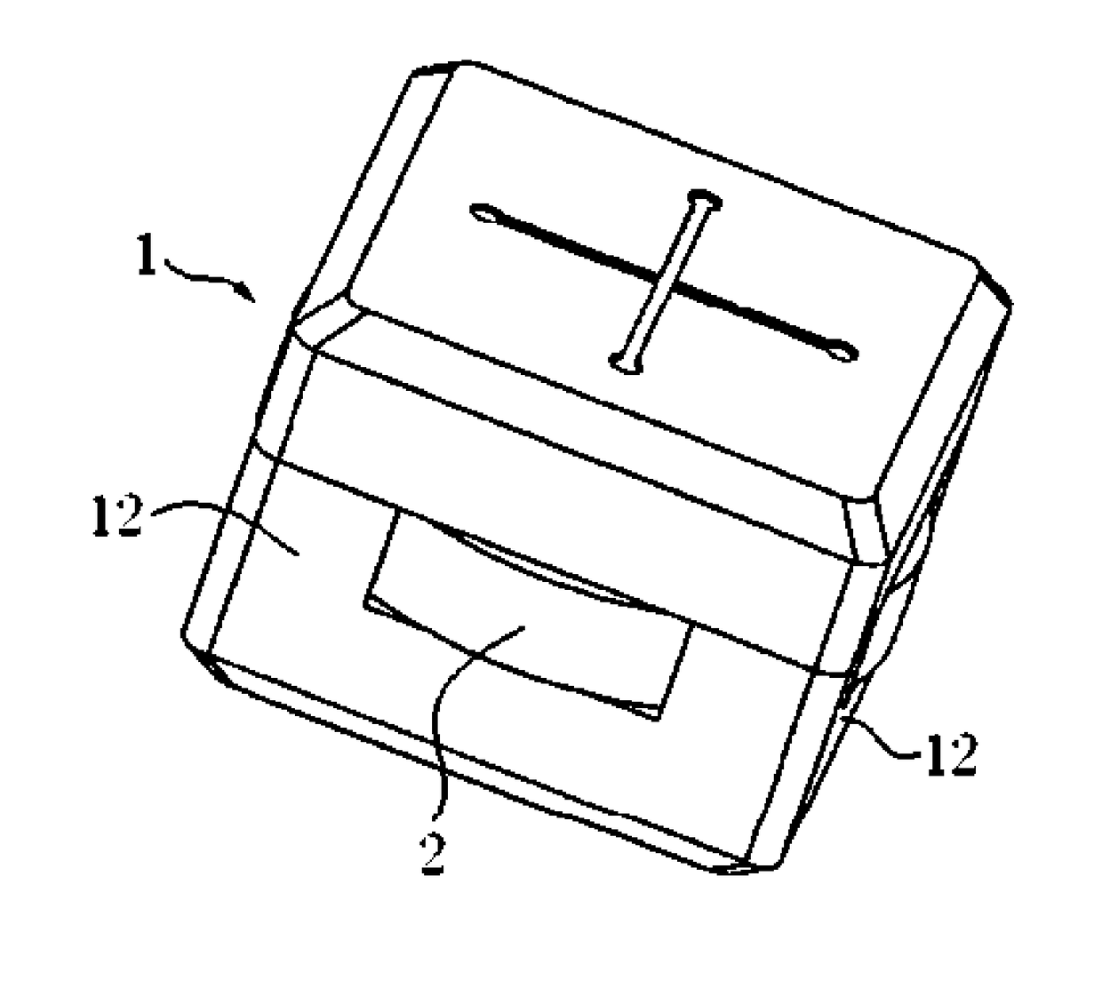
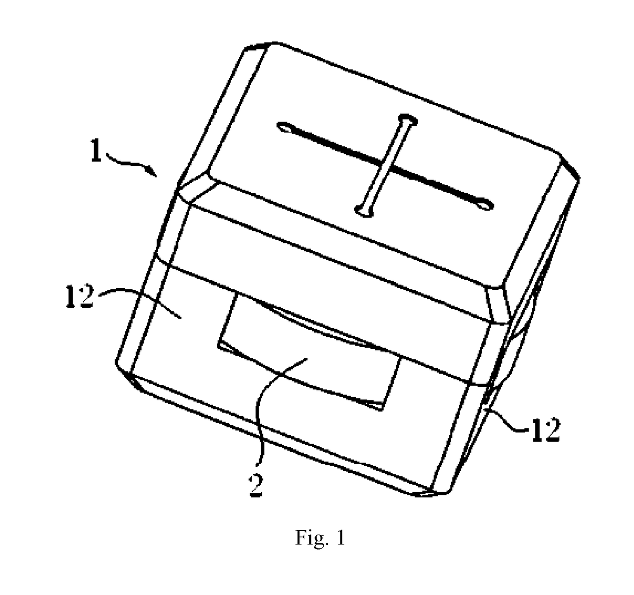
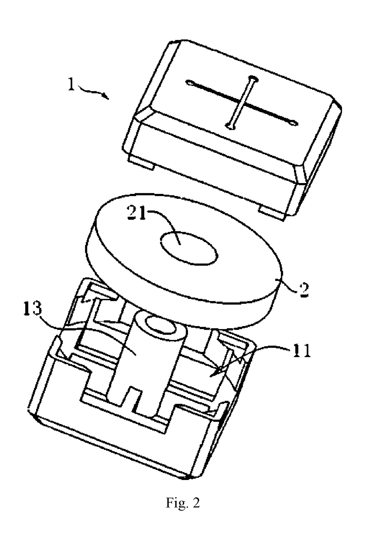
[0034]As shown in FIGS. 1 and 2, the magnetically connected block in this embodiment includes an electrically conductive connector 1. The electrically conductive connector 1 includes an upper casing and a lower casing fixedly connected to each other. The upper casing and the lower casing form a cavity 11. A central pillar 13 is provided in the cavity 11. The central pillar 13 and the lower casing form an integral structure. A magnet 2 magnetized radially is provided in the cavity 11. The magnet 2 is cylindrical. An axial through-hole 21 is provided at the center of the magnet 2. The central pillar 13 passes through the axial through-hole 21 which cause the magnet 2 rotatable in the cavity 11 about the central axis. Four side surfaces of the electrically conductive connector 1 are all contact surfaces 12. The contact surface 12 is provided with an opening. The radial edge of the magnet 2 projects from the opening. That is, the diameter of the magnet 2 is greater than the length and w...

embodiment 2

[0036]As shown in FIGS. 3 and 4, the magnetically connected block in this embodiment includes an electrically conductive connector 1, a casing 6 and a functional circuit 4. The functional circuit 4 is installed on the casing 6. The upper part of the casing 6 is fixedly provided with a cover 7. A function execution device of the functional circuit 4 is located in the cover 7. There may be a plurality of electrically conductive connectors 1 as required. The function execution device of the functional circuit 4 may be a battery, a light-emitting module, a switch module, a sliding rheostat module, a sounding module, a resistor, an inductor, a capacitor, a motor, a switch and the like, which are provided according to the particular function requirements of the block.

[0037]The two ends of the casing 6 are connected to the electrically conductive connector 1 respectively. The electrically conductive connector 1 includes an upper casing and a lower casing fixedly connected to each other. Th...

embodiment 3

[0039]As shown in FIGS. 5 and 6, the magnetically connected block in this embodiment is substantially the same as that of the embodiment 2. The differences lie in that, in this embodiment, there is no central pillar in the cavity 11 and there is no central axial hole in the magnet 2. The functional circuit 4 is a power circuit and an indicator circuit. Two electrically conductive connectors 1 are located at the same side of the block. The electrically conductive connectors 1 are a positive connector and a negative connector.


PUM


Abstract

A magnetically connected block, including an electrically conductive connector, the electrically conductive connector defining therein a cavity and a magnet being arranged in the cavity, the electrically conductive connector being provided with a contact surface and a conductive device being provided on the contact surface. In this way, the electrically conductive connector achieves the electrical conduction between blocks by way of the conductive device and achieves the connection between two blocks by way of the magnet to ensure the connection by attraction and the electrical connection between blocks. Owing to the arrangement of the magnet, blocks can be attracted onto a magnetic attraction board surface to facilitate teaching use.

Description

FIELD OF THE INVENTION[0001]The present invention relates to splicing toys, and more particularly to a magnetically connected block.BACKGROUND OF THE INVENTION[0002]Learning through electronic blocks is intuitive and interesting. Electronic splicing devices may be applied to the real life. Electronic blocks show complex electronic circuitry knowledge to the children visually through simple blocks so that they can experience the interest of the electronic world and children at different ages can learn contents with different difficulties.[0003]Electronic blocks on the current market and in the prior art are unique and splicable accessories connected through unique snap fasteners which fix electronic components such as wires, lamps, diodes, triodes, resistors, capacitors, various switches, electric meters, motors, loudspeakers, integrated blocks, etc. on a plastic plate (block).[0004]Chinese patent No. CN2245796Y “Universal electronic block” discloses all techniques of this traditiona...

Claims


Application Information

Patent Timeline
Patent Type & Authority Applications(United States)
IPC IPC(8): A63H33/04A63H33/10A63H33/26
CPCA63H33/042A63H33/10A63H33/046A63H33/26
Inventor WEI, ZHENGPENG
Owner SHENZHENSHI HANTONG TECH CO LTD
Why Eureka
Try Eureka