Refrigeration cycle device
a refrigeration cycle and cycle technology, applied in the direction of refrigeration components, mechanical equipment, light and heating equipment, etc., can solve the problems of global warming, low stability of r1123 and r1132, and drawbacks of r410a use, and achieve the effect of high reliability of the refrigeration cycle devi
- Summary
- Abstract
- Description
- Claims
- Application Information
AI Technical Summary
Benefits of technology
Problems solved by technology
Method used
Image
Examples
first exemplary embodiment
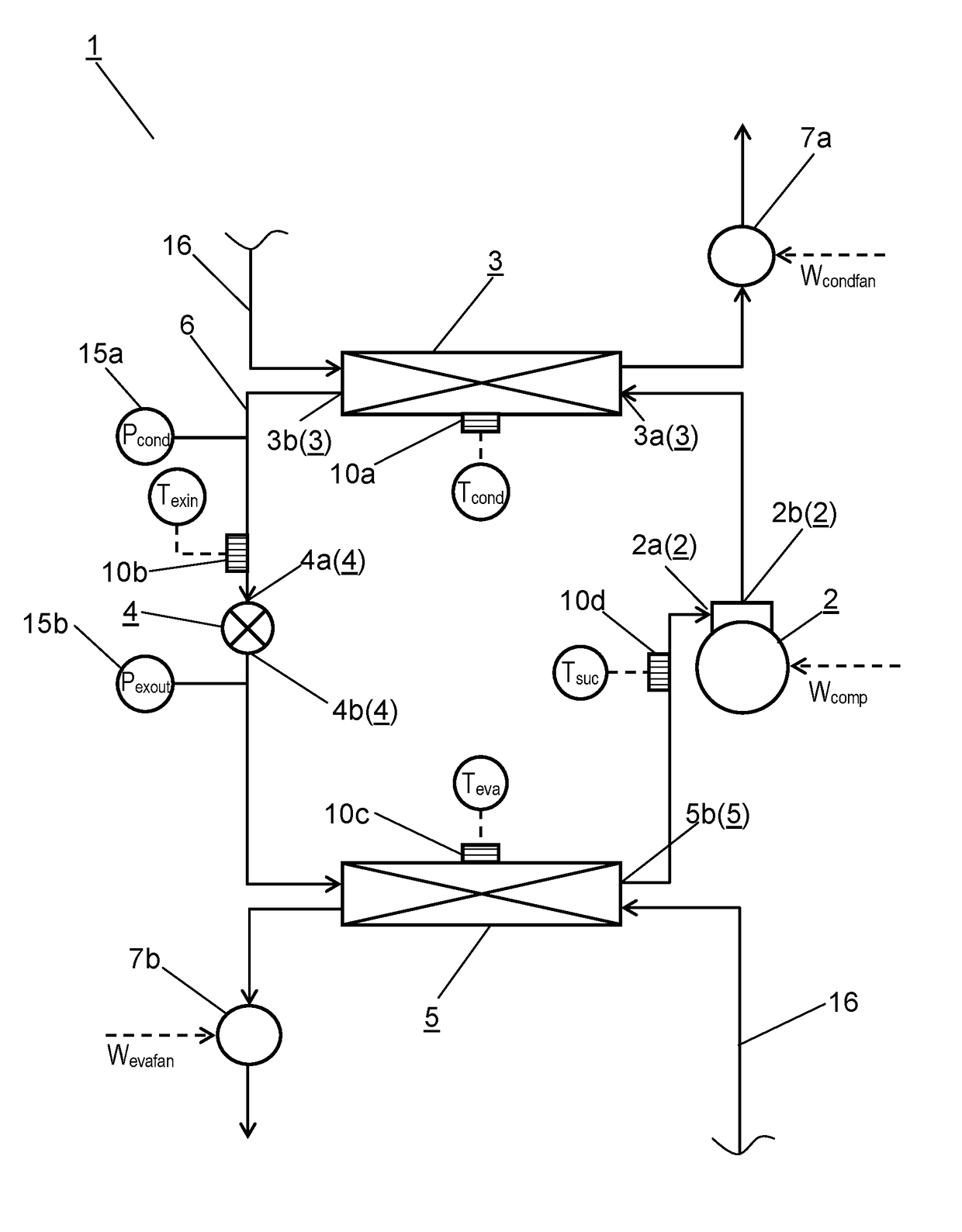
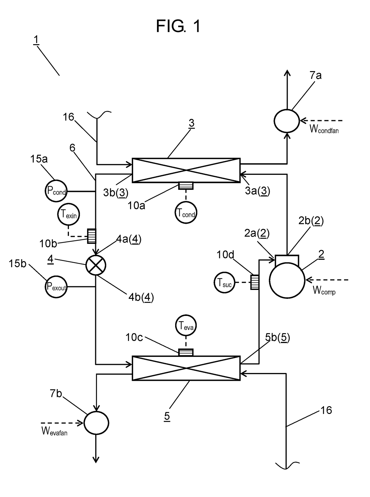
[0032]A refrigeration cycle device according to a first exemplary embodiment of the present invention is described with reference to FIG. 1.
[0033]FIG. 1 is a schematic constitutional view of a refrigeration cycle device according to the first exemplary embodiment of the present invention.
[0034]As shown in FIG. 1, refrigeration cycle device 1 according to this exemplary embodiment is formed of at least compressor 2, condenser 3, expansion valve 4, evaporator 5, refrigerant pipe 6, fluid passage 16 of surrounding mediums and the like. A refrigeration cycle circuit is formed by sequentially connecting these constitutional elements by refrigerant pipe 6. In such a configuration, a working fluid (refrigerant) described hereinafter is sealed in the refrigeration cycle circuit.
[0035]First, a working fluid used in the refrigeration cycle device according to this exemplary embodiment is described.
[0036]A working fluid sealed in refrigeration cycle device 1 is formed of a mixed fluid of a two...
second exemplary embodiment
[0154]A refrigeration cycle device according to a second exemplary embodiment of the present invention is described with reference to FIG. 9.
[0155]FIG. 9 is a schematic constitutional view of the refrigeration cycle device according to the second exemplary embodiment of the present invention.
[0156]As shown in FIG. 9, refrigeration cycle device 20 according to this exemplary embodiment differs from refrigeration cycle device 1 according to the first exemplary embodiment with respect to a point that high-pressure-side pressure detecting part 15a is disposed between a discharge portion of compressor 2 and an inlet of condenser 3. Other constitutions and operations of refrigeration cycle device 20 of this exemplary embodiment are equal to corresponding constitutions and operations of refrigeration cycle device 1 of the first exemplary embodiment and hence, the description of such other constitutions and operations is omitted.
[0157]As shown in FIG. 9, to consider a flow direction of a wo...
third exemplary embodiment
[0159]A refrigeration cycle device according to a third exemplary embodiment of the present invention is described hereinafter with reference to FIG. 10.
[0160]FIG. 10 is a schematic constitutional view of the refrigeration cycle device according to the third exemplary embodiment of the present invention.
[0161]As shown in FIG. 10, refrigeration cycle device 30 according to this exemplary embodiment further includes bypass flow passage 13 which includes bypass open / close valve 13a connected to inlet 4a and outlet 4b of expansion valve 4. Further, refrigeration cycle device 30 of this exemplary embodiment differs from refrigeration cycle device 1 according to the first exemplary embodiment with respect to a point that a purge line which has relief valve 14 forming an atmosphere open portion is provided between outlet 3b of condenser 3 and inlet 4a of expansion valve 4. In this case, an open side of relief valve 14 is disposed outdoors. In FIG. 10, the description of condensation temper...
PUM
 Abstract
Description
Claims
Application Information
 - R&D
- Intellectual Property
- Life Sciences
- Materials
- Tech Scout
- Unparalleled Data Quality
- Higher Quality Content
- 60% Fewer Hallucinations
Browse by: Latest US Patents, China's latest patents, Technical Efficacy Thesaurus, Application Domain, Technology Topic, Popular Technical Reports.
© 2025 PatSnap. All rights reserved.Legal|Privacy policy|Modern Slavery Act Transparency Statement|Sitemap|About US| Contact US: help@patsnap.com


