
Arc flash detection device having optic fiber sensor

a detection device and optic fiber technology, applied in measurement devices, dielectric strength testing, instruments, etc., can solve the problems of electrical shock of managers or workers, increase labor costs, power loss and huge fire disasters,

Inactive Publication Date: 2017-05-18
G2 POWER CO LTD
View PDF3 Cites 7 Cited by
  • Summary
  • Abstract
  • Description
  • Claims
  • Application Information

AI Technical Summary

Benefits of technology

The present invention aims to provide an arc flash detection device and method for a power receiving and distributing facility. The device can detect an arc flash and prevent it from occurring, ensuring the stability and reliability of the power facility. This will allow for the safe operation of the power receiving and distributing facility.

Problems solved by technology

Like this, the worker who receives the monitoring result from the central monitoring station should always stay at the workplace so as to monitor the state of power, which raises the labor cost, and further, if an appropriate action is not taken by the worker, power loss and huge fire disasters may happen.
As a result, the manager or worker may be electrically shocked, and further, various safety accidents may frequently happen.
Accordingly, the normal arc flash (that is, the arc flash generated at the outside) generated by normal causes may be erroneously sensed as the arc flash generated due to accidents or insulation deterioration from the interior of the power receiving and distributing facility.
Accordingly, the power receiving and distributing facility in Patent Document 1 may drive the circuit breaker or issue a danger warning unnecessarily.
As a result, power failure is unnecessarily done, thus making it hard to conduct the maintenance of the power receiving and distributing facility and the normal operation of the loads.
According to the above-mentioned conventional practice, however, even if the optical fiber and the fluorescent filter are mounted on the arc flash sensor, it is extremely difficult to completely block the outside light introducible to the arc flash sensor according to the characteristics of light.
On the other hand, separate devices for perfectly blocking the outside light may be disposed on the power receiving and distributing facility, but the distance between the devices disposed in the power receiving and distributing facility may be decreased to give bad influences on the insulation properties of the power receiving and distributing facility and to increase the volume of the power receiving and distributing facility.
As a result, the power receiving and distributing facilities according to Patent Documents 1 and 2 cannot precisely detect the strength of the arc flash, thus unnecessarily causing the circuit breaker to be driven or issuing the danger warning.
Accordingly, power failure is unnecessarily done, thus making it hard to conduct the maintenance of the power receiving and distributing facility and the normal operation of the loads.

Method used


Image

  • Arc flash detection device having optic fiber sensor
  • Arc flash detection device having optic fiber sensor
  • Arc flash detection device having optic fiber sensor

Examples


Embodiment Construction

[0044]Hereinafter, an explanation on an arc flash detection device and method according to the present invention will be in detail given with reference to the attached drawing.

[0045]The present invention may be modified in various ways and may have several exemplary embodiments. Specific exemplary embodiments of the present invention are illustrated in the drawings and described in detail in the detailed description. However, this does not limit the invention within specific embodiments and it should be understood that the invention covers all the modifications, equivalents, and replacements within the idea and technical scope of the invention.

[0046]Terms, such as the first, the second, A, and B, may be used to describe various elements, but the elements should not be restricted by the terms. The terms are used to only distinguish one element from the other element. For example, a first element may be named a second element without departing from the scope of the present invention. ...


PUM


Abstract

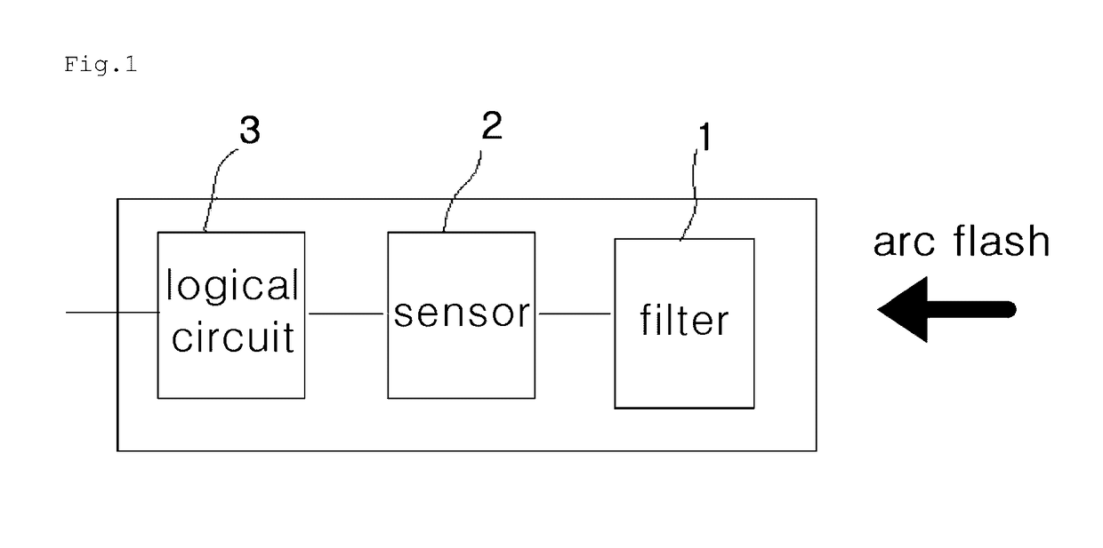
The present invention relates to an arc flash detection device for detecting the generation of an arc flash in a power receiving and distributing facility and for generating a trip signal upon the generation of the arc flash, including: optical fiber cables for transmitting an arc flash detection optical signal and receiving an arc flash optical signal converted by the arc flash; a lens part having a reflection element adapted to reflect the arc flash detection optical signal transmitted through the optical fiber cables and the arc flash optical signal converted by the arc flash if the arc flash is generated; and an optical detection part for transmitting the arc flash detection optical signal through the optical fiber cables and comparing the arc flash optical signal received through the lateral periphery of one side optical fiber cable and the arc flash optical signal reflected on the lens part with the arc flash detection optical signal to output an arc flash generation signal as a difference signal between the compared results.

Description

BACKGROUND OF THE INVENTION[0001]Field of the Invention[0002]The present invention relates to an arc flash detection device and method that detects an arc flash in high and low voltage distribution panels, a motor control panel, and a panel board (which are referred to as “power receiving and distributing facility”) in which high and low voltage electricity is received and distributed, and more particularly, to an arc flash detection device and method that is provided with an optical system having a line sensor and a loop sensor to detect an arc flash.[0003]Background of the Related Art[0004]In various workplaces like factories, schools and buildings, equipment, which works with power supplied thereto, generally includes a body for supplying the power, a work machine for receiving the power from the body to really perform a given work, and a cable for transmitting the power from the body to the work machine.[0005]In most workplaces, the body and the work machine of the equipment are...

Claims


Application Information

Patent Timeline
Patent Type & Authority Applications(United States)
IPC IPC(8): G01R31/12
CPCG01R31/1272H02H1/0023
Inventor KIM, YOUNG IL
Owner G2 POWER CO LTD
Learn More