Atomic oscillator and temperature control method of atomic oscillator

a technology of atomic oscillator and temperature control method, which is applied in the direction of instruments, horology, semiconductor lasers, etc., can solve problems such as temperature changes in gas cells

Active Publication Date: 2017-05-18
MICROCHIP TECH INC
View PDF2 Cites 12 Cited by
  • Summary
  • Abstract
  • Description
  • Claims
  • Application Information

AI Technical Summary

Benefits of technology

[0029]According to the above-mentioned application example, a control current of the temperature adjustment unit which is applied from the second temperature control unit can make the temperature adjustment unit operate as a cooling unit as a normal state.

Problems solved by technology

However, an external environment in which the atomic oscillator including the gas cell is installed, particularly, a temperature environment causes changes in temperature within the gas cell.

Method used


Image

  • Atomic oscillator and temperature control method of atomic oscillator
  • Atomic oscillator and temperature control method of atomic oscillator
  • Atomic oscillator and temperature control method of atomic oscillator

Examples


first embodiment

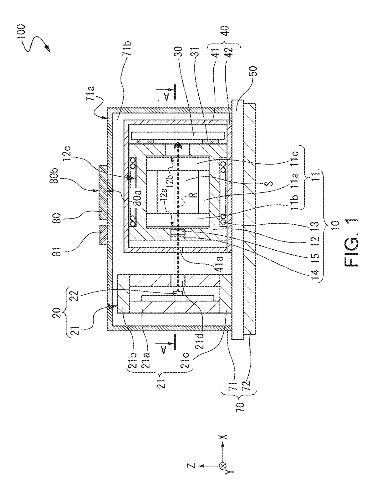
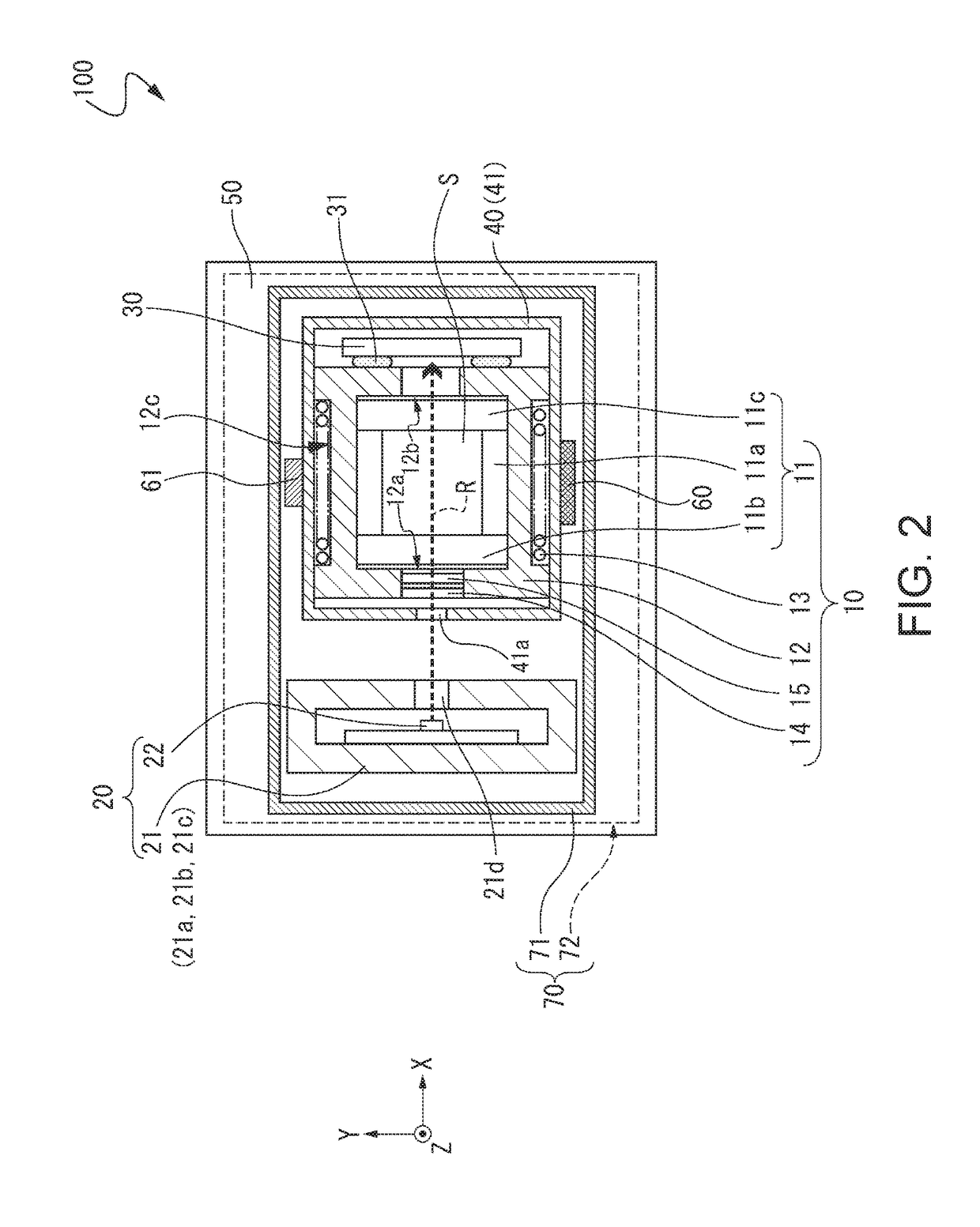
[0044]FIGS. 1 and 2 show an outline of an atomic oscillator according to a first embodiment, FIG. 1 is a front cross-sectional view, and FIG. 2 is a cross-sectional view taken along line A-A′ shown in FIG. 1.

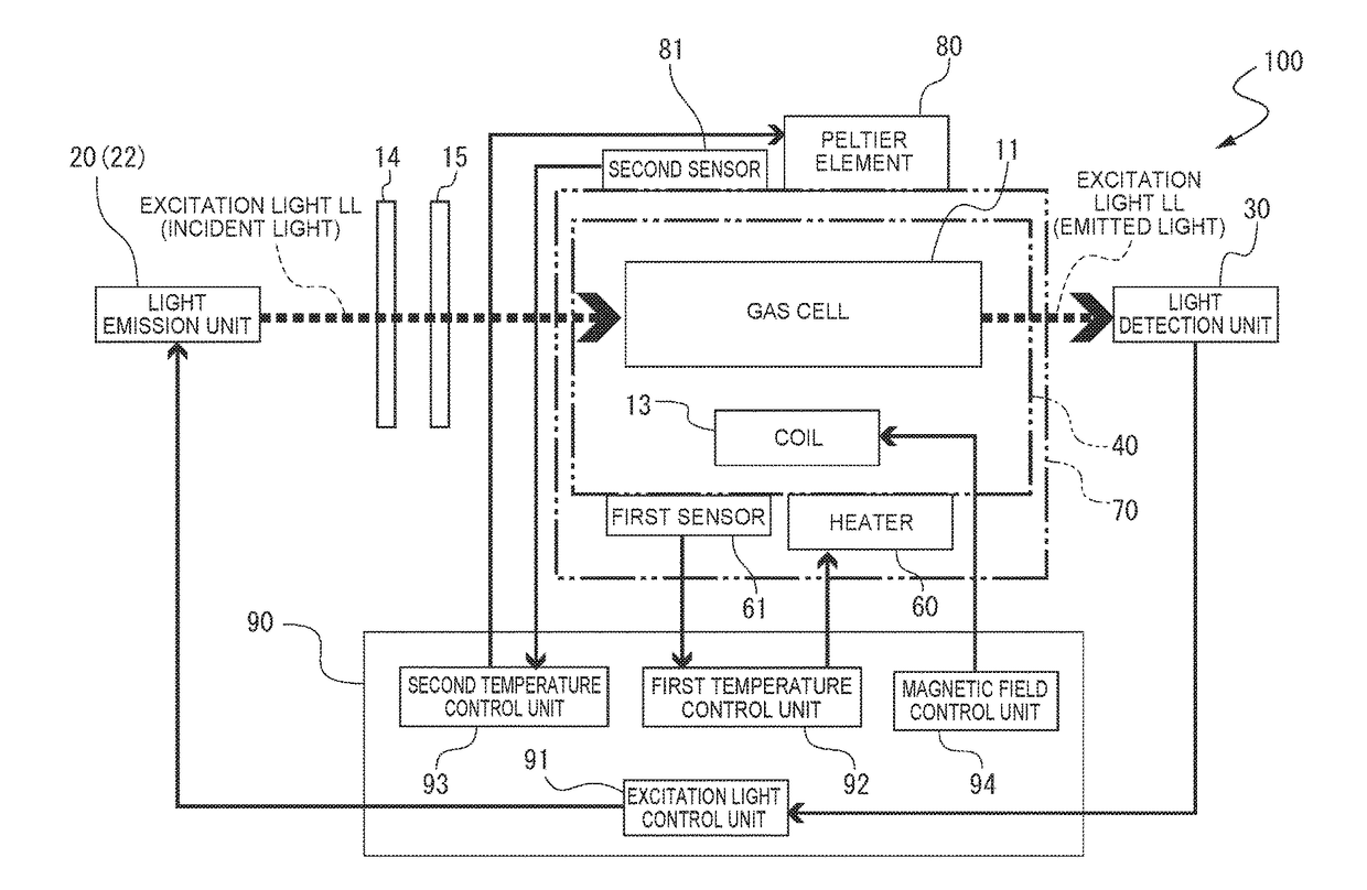
[0045]An atomic oscillator 100 shown in FIGS. 1 and 2 is an atomic oscillator using a quantum interference effect. The atomic oscillator 100 includes a gas cell unit 10, a light emission unit 20, and a first magnetic shield 40 that accommodates the gas cell unit 10 and has a magnetic shielding property in the atomic oscillator 100 according to this embodiment.

[0046]The gas cell unit 10 includes a gas cell 11, a gas cell holding member 12 that holds the gas cell 11 and transmits heat generated by a heater to be described later to the gas cell 11, and a coil 13 which is wound around the outer circumferential surface of the gas cell holding member 12 along the X-axis direction. In the gas cell 11, an internal space S is formed by a main body 11a having a columnar through hole and a...

second embodiment

[0078]As a second embodiment, a temperature control method of the atomic oscillator 100 according to the first embodiment will be described. As shown in FIG. 6 showing a control management diagram and a heater current control diagram which indicate the control of temperature of a gas cell in the related art, a start-up current is applied to a heater at the time of supplying power to an atomic oscillator (s0), an increase and decrease in a current applied to the heater are repeated until it is detected that a gas cell sensor detection temperature tp (hereinafter, referred to as a detection temperature tp) is stabilized at a gas cell control temperature Tp (hereinafter, referred to as a control temperature Tp), and a current applied to the heater has a stabilized value from a time s1 at which the control temperature Tp is stably detected on the basis of the detection temperature tp.

[0079]However, when the external temperature ts of the gas cell starts to rise after a time s2, a curren...

third embodiment

[0090]FIG. 8 is a schematic diagram showing a basic configuration of an atomic oscillator 200 according to a third embodiment. Meanwhile, the atomic oscillator 200 according to this embodiment is different from the atomic oscillator 100 according to the first embodiment in terms of a configuration of the control unit 90 described in FIG. 3, and other configurations thereof are the same as those in the configurations shown FIGS. 1 and 2. Therefore, the same components are denoted by the same reference numerals and signs as those in the atomic oscillator 100 according to the first embodiment, and a description thereof will not be repeated.

[0091]As shown in FIG. 8, a control unit 210 is provided with an excitation light control unit 91, a first temperature control unit 92, and a magnetic field control unit 94 that are the same as in the described above control unit 90 of the atomic oscillator 100 according to the first embodiment. In addition, the control unit 210 includes a second tem...


PUM


Abstract

An atomic oscillator includes at least a gas cell that has metal atoms sealed therein, a coil that is disposed in a vicinity of the gas cell, a first magnetic shield that accommodates the gas cell and the coil therein, a second magnetic shield that accommodates a heater heating the gas cell, a first temperature sensor detecting a temperature of the gas cell, and the first magnetic shield therein, and a temperature adjustment unit and a second temperature sensor that are disposed outside the second magnetic shield.

Description

CROSS REFERENCE[0001]This application claims the benefit of Japanese Application No. 2015-222777, filed on Nov. 13, 2015. The disclosure of the prior application is hereby incorporated by reference herein in its entirety.BACKGROUND[0002]1. Technical Field[0003]The present invention relates to an atomic oscillator and a temperature control method of an atomic oscillator.[0004]2. Related Art[0005]An atomic oscillator is known which oscillates on the basis of energy transfer of atoms of an alkali metal such as rubidium or cesium. In general, an operating principle of the atomic oscillator is classified broadly into a method using a double resonance phenomenon based on light and microwaves and a method using a quantum interference effect (CPT: coherent population trapping) based on two types of light beams having different wavelengths.[0006]In any type of atomic oscillator, an alkali metal is sealed in a gas cell together with a buffer gas, a detector provided on a side opposite to the ...

Claims


Application Information

Patent Timeline
Patent Type & Authority Applications(United States)
IPC IPC(8): H03L7/26H03L1/02
CPCH03L1/02H03L7/26G04F5/145H01S5/02257
Inventor TANAKA, NORIAKICHINDO, KOJI
Owner MICROCHIP TECH INC
Why Eureka
Try Eureka