Torch handle including pneumatically operated jaw

a technology of pneumatic operation and handle, which is applied in the direction of electrode supporting devices, non-shielding electrode holders, manufacturing tools, etc., can solve the problems of periodic replacement of electrodes, grooves or gouges left on the surface of workpieces, and wear of electrodes of gouging torch, so as to reduce the hand gripping force typically required for operating the gouging torch lever

Active Publication Date: 2017-05-25
VICTOR EQUIP
View PDF18 Cites 3 Cited by
  • Summary
  • Abstract
  • Description
  • Claims
  • Application Information

AI Technical Summary

Benefits of technology

[0007]Exemplary approaches herein provide a torch handle including a pneumatically controlled jaw operable to engage an electrode. In one approach, a system is provided for distributing gas within the torch handle, the system including a pneumatic cylinder disposed within a main housing of the torch handle. The pneumatic cylinder may include a piston coupled to a shaft for actuating a first member of a jaw relative to a second member of the jaw. The system further includes a gas passageway through the main housing, the gas passageway including an exit orifice disposed within the second member of the jaw. A flow controller is operable to control a flow of gas and direct it to either the pneumatic cylinder or the gas passageway. In one approach, the first member is actuated towards the second member when the flow of gas is directed through the gas passageway, and actuated away from the second member when the flow of gas is directed to the pneumatic cylinder. By providing a pneumatically assisted jaw, the hand gripping force typically required for operating the gouging torch lever may be greatly reduced.

Problems solved by technology

As metal melts under the influence of the arc, a stream of high-pressure air directed along the electrode to the arc causes the molten metal to be forcibly removed from the influence of the arc, thus leaving a groove or gouge in the surface of the workpiece.
The electrodes of the gouging torch exhibit wear, however, and must be periodically replaced.
This leads to operator fatigue, especially over a large number of cycles, as the hand gripping force necessary on the gouging torch lever may be significant.

Method used


Image

  • Torch handle including pneumatically operated jaw
  • Torch handle including pneumatically operated jaw
  • Torch handle including pneumatically operated jaw

Examples


Embodiment Construction

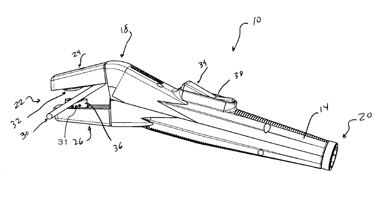
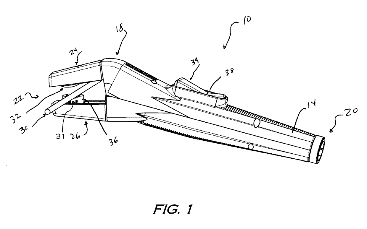
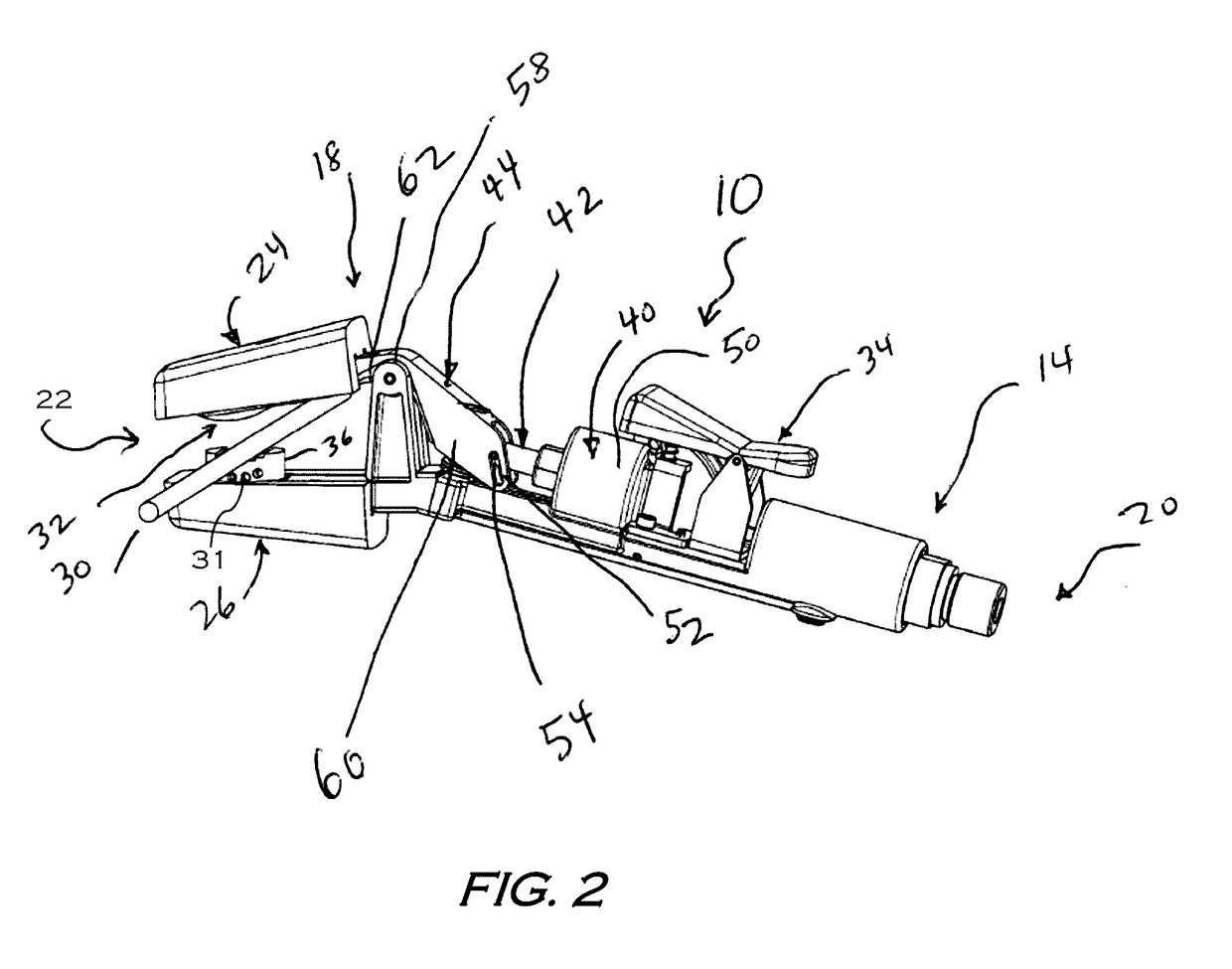
[0023]The present disclosure will now proceed with reference to the accompanying drawings, in which various approaches are shown. It will be appreciated, however, that the disclosed torch handle may be embodied in many different forms and should not be construed as limited to the approaches set forth herein. Rather, these approaches are provided so that this disclosure will be thorough and complete, and will fully convey the scope of the disclosure to those skilled in the art. In the drawings, like numbers refer to like elements throughout.

[0024]As used herein, an element or operation recited in the singular and proceeded with the word “a” or “an” should be understood as not excluding plural elements or operations, unless such exclusion is explicitly recited. Furthermore, references to “one approach” of the present disclosure are not intended to be interpreted as excluding the existence of additional approaches that also incorporate the recited features.

[0025]Furthermore, spatially ...


PUM

PropertyMeasurementUnit
pressureaaaaaaaaaa
lengthaaaaaaaaaa
rotationaaaaaaaaaa

Abstract

Approaches herein provide a torch handle including a pneumatically controlled jaw operable to engage an electrode. In one approach, a system is provided for distributing gas within the torch handle, the system including a pneumatic cylinder within a main housing of the torch handle. The pneumatic cylinder is coupled to a shaft for actuating first and second members of the jaw. The system further includes a gas passageway through the main housing, the gas passageway extending to an exit orifice disposed within the second member. A flow controller, including first and second valves, is operable to direct a flow of a gas to either the pneumatic cylinder or the gas passageway. In one approach, the first member is actuated towards the second member when the gas is directed through the gas passageway, and actuated away from the second member when the gas is directed to the pneumatic cylinder.

Description

BACKGROUND OF THE DISCLOSURE[0001]Field of the Disclosure[0002]The present disclosure relates generally to a gouging torch. More particularly, the present disclosure relates to a gouging torch having a torch handle with a pneumatically operated jaw.[0003]Discussion of Related Art[0004]Air carbon-arc systems and processes may be used in a wide variety of applications, such as metal fabrication and casting finishing, chemical and petroleum technology, construction, mining, general repair, and maintenance. With respect to metal fabrication and casting finishing, air carbon-arc metal removing systems and processes may be used to gouge, groove, cut, or flush metal from a surface.[0005]An air carbon-arc cutting and gouging torch may operate by positioning an electrode relative to a workpiece so that an electric arc can be struck and maintained between the electrode and the workpiece. As metal melts under the influence of the arc, a stream of high-pressure air directed along the electrode ...

Claims


Application Information

Patent Timeline
Patent Type & Authority Applications(United States)
IPC IPC(8): B23K9/28
CPCB23K9/282B23K9/28B23K9/013B23K9/173B23K9/287
Inventor STEPHENS, MICHAEL E.HENDERSON, JEFFREY S.
Owner VICTOR EQUIP
Why Eureka
Try Eureka