Gripper device, and use of a gripper device

a gripper device and gripper body technology, applied in the direction of gripping heads, manipulators, program-controlled manipulators, etc., can solve the problems of limiting the effective service life, affecting the dynamic behaviour of the gripper device, and consuming time and costs, so as to improve the mechanical dynamic properties of the device, improve the structure of the gripper body implementing the gripper device, and not impair the dynamic properties of the system

Active Publication Date: 2017-08-10
ETO MAGNETIC GMBH
View PDF2 Cites 2 Cited by
  • Summary
  • Abstract
  • Description
  • Claims
  • Application Information

AI Technical Summary

Benefits of technology

[0010]The obvious advantage of this inventive measure lies firstly in the fact that the magnetic field generating means for the magnetic interaction with the actuator means, that is to say, for the application of a magnetic field to the latter, do not contribute to the moved mass (since they are no longer moved parts of the gripper device); they do not have to be accelerated, and thus significantly improve the mechanical dynamic properties of the device. In addition, the structure of a gripper body implementing the gripper device is significantly simplified, since the latter, in its simplest form, must only implement the contact sections, and accommodate or anchor the actuator means acting on the first contact section with the drive force appropriately; in contrast, for example, electromagnetic coil means, together with electrical supply cables, additionally or alternatively permanent magnetic means (potentially heavy and brittle, and therefore vulnerable to impact) are also provided as typical magnetic field generating means; these are static and therefore immovable, and are accordingly no longer subject to significant wear phenomena, and, as described, do not impair the dynamic properties of the system.
[0011]Within the scope of possible implementations of the invention, the inventive operative pairing is to be understood in broad and comprehensive terms; it is to include both a clamping action, a frictional action, or similar lateral engagement of the first and / or second contact sections with an appropriate (external) surface of the workpiece (which can assume almost any configuration), and also an accompaniment action (enabling a form fit), an engagement or interlock in appropriate grooves, undercuts, projections or similar engagement sections of the workpiece, wherein the first and / or second contact section can then be appropriately contoured or configured in accordance with a desired action in the course of the gripping or holding process.
[0012]It is also within the scope of a preferred development of the invention to implement the contact sections by means of a gripper acting in a pincer-like manner, and it is further preferred to provide gripping jaws and / or gripping arms for purposes of gripping and / or holding the workpiece; this configuration, while it is indeed preferred, is not to be understood as restrictive. However, in a further preferred configuration, with a flat gripper body formed, for example, from a metallic and / or plastic material, an implementation of the invention is enabled that combines ease of manufacture and high continuous load-bearing ability with insensitivity to disturbances and low production costs. Here a single-piece design is conceivable (for example, in the form of a yoke implemented in terms of injection moulding of the plastic material, with arms to form the contact sections, wherein an MSM body is appropriately positioned as the actuator means between the elastically movable arms), alternatively a design with one or more hinged or articulated sections between components of a multi-part gripper body would also be conceivable, wherein these sections then in turn connect the mechanical components implementing the contact sections at a suitable location for purposes of producing and applying the drive force. Depending on the material to be employed in the implementation of the gripper body and its suitability for deformation (for example in the case of a gripper that is to be implemented in one piece), or for a multipart design, the person skilled in the art will select the appropriate design and configuration according to the particular manipulation requirement, wherein implementation of the inventive actuator by means of an elongated (single- or multi-part) body for purposes of a magnetic field-induced expansion or contraction in the direction of extension is also a preferred variant, although the invention is not restricted to such forms of embodiment.
[0013]In the practical implementation of the invention and in accordance with further developments, it has been found to be preferable to assign reset means and / or spring means to the actuator means, in particular on or in the gripper; in terms of their force behaviour these means are superimposed onto the force of the actuator means; in the simplest case, for example, a spring can be mechanically tensioned in parallel with an MSM body between the arms or jaws implementing the contact sections of the gripper device. The said spring means can then be appropriately dimensioned and set up to enable the holding of the workpiece even after the application of the magnetic field to the actuator means has terminated (that is to say, after an electrical deactivation of an electromagnet, or after a spatial movement of the gripper device from a magnetically active engagement with the static magnetic field generating means provided). If the application of the magnetic field is terminated, for example after a magnetic field-induced expansion of a body, the body remains in the expanded position, but a (continued) application of force to a workpiece sitting on a driven contact section is, as a general rule, no longer possible. Here, for example, a (permanent) spring force of a tension or compression spring, appropriately introduced previously, would then act, and would thus promote the inventive holding of the workpiece within the scope of the system.
[0014]In the concrete configuration of the said reset means or spring means in accordance with further developments (wherein, instead of a—mechanical—spring, for example, it is also possible to employ e.g. oppositely directed shape-memory alloy materials to which a magnetic field can be applied), in a further development provision is firstly and advantageously made to set up the reset or spring forces of the said reset or spring means such that they enable a compression (reset) of an MSM body expanded by magnetic field action in the state in which no field is applied. In this case, however, the application of the magnetic field always has to overcome the said reset (spring) in the course of an expansion of the actuator means; however, an MSM body arrangement can advantageously be implemented in which application of the magnetic field only takes place one-dimensionally and perpendicularly to an expansion direction (and thus typically a longitudinal direction or extension direction of an elongated design of actuator crystal). Since, in addition to the spring properties, the magnetomechanical properties of the MSM body are also relevant in the design and conception, the so-called twinning stress, that is to say, the mechanical force required for a reset without a magnetic field, would be appropriately configured in this variant by the choice of material and matched to the spring force.
[0015]The same applies for an alternative procedure with the implementation of associated reset means or spring means to the actuator means. If these are set up such that the gripper therewith provided remains in its activated position after the application of the magnetic field (and is not reset by the reset means or spring means, for example because the latter have a weaker spring force compared with the twinning stress), a potentially high gripping force on or onto the workpiece ensues with a correspondingly high designed or set up value of twinning stress. A reset (or closure) of this configuration would then preferably take place by the application of a magnetic field in a direction orthogonal to the direction of the first magnetic field; this can be provided by appropriate configuring and / or positioning of magnetic field generating means, for example at a second position along the movement path, enabling a release and / or delivery. The advantage of this variant is that a gripper device implemented in this manner does not first have to be opened and / or moved from an initial position (in this respect monostable), which in turn can provide potential speed advantages. However, since the gripping force is essentially determined by the twinning stress of the material, it is potentially lower than in the case of the variant first discussed.

Problems solved by technology

However, such additional infrastructures of lines and cables are subject to loads promoting high wear, in particular in cases of high accelerations, large numbers of movement cycles, and / or in cases of systems deployed in stressful environments, which loads often limit the effective service lives of systems that are implemented in this manner, and / or determine maintenance and overhaul cycles, with corresponding expenditure of time and costs, which result in a need for improvement, in particular in industrial conveyor systems, logistics and production environments.
Moreover the generic provision of the infrastructure of lines, cables and drives as described on gripper devices of known art causes moving components, such as, for example, the arms or jaws forming the first and second contact sections, to be additionally loaded by the masses that are being moved, with the result that the dynamic behaviour of the gripper device is impaired.
Thus, for example, the potential (switching) speed advantages of a magnetic MSM actuator are thereby in part in turn negatively affected by the fact that in the context of the overall system the coil means required for the application of a magnetic field onto the MSM crystal, together with the supply lines, increase the mechanical inertia of the overall system.
The same is true for electromotive or pneumatic actuator means, whose ability to move (and to accelerate) is impaired or limited in the same manner by the infrastructure of supply lines and cables as discussed.

Method used


Image

  • Gripper device, and use of a gripper device
  • Gripper device, and use of a gripper device
  • Gripper device, and use of a gripper device

Examples


Embodiment Construction

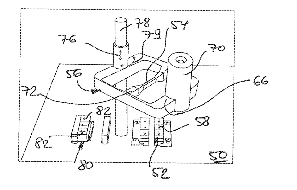
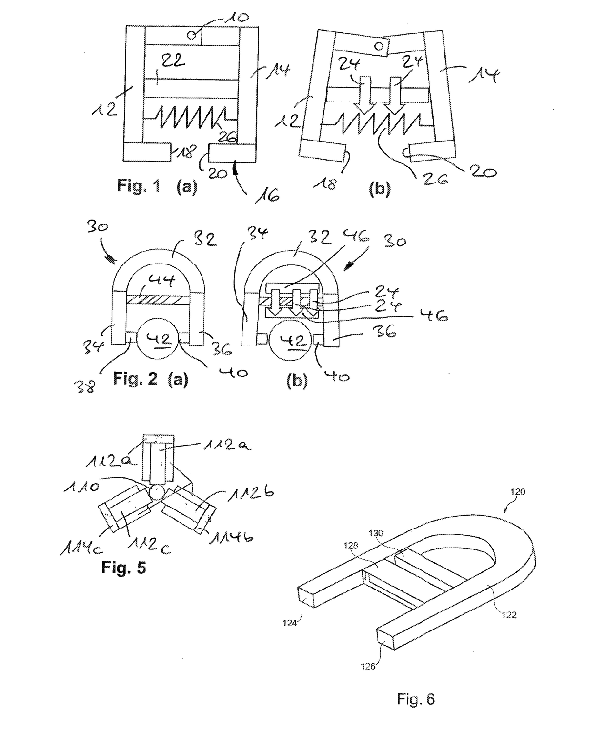
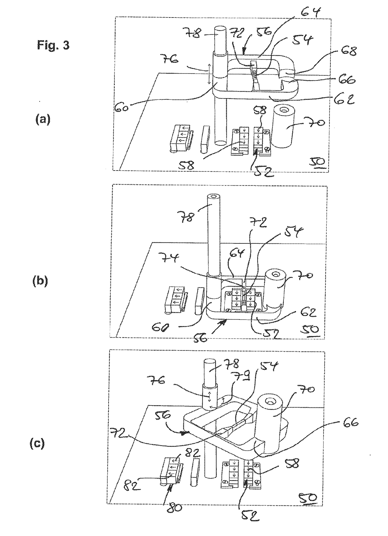
[0027]Possible basic configurations of the present invention (not exhaustive with regard to the breadth of variants) are explained with the aid of FIGS. 1 and 2. Thus, a gripper device schematically shown in the first example of embodiment of FIG. 1 has a gripper 16 formed by two gripping arms 12, 14, which are connected to one another such that they can pivot about a joint 10, and which by means of a pair of jaw sections 18 and 20 formed on the free ends of the arms 12, 14 have contact sections for purposes of interaction with a workpiece (not shown in FIG. 1).

[0028]An MSM crystal body 22, which is designed in the elongated manner as shown from an NiMnGa alloy exhibiting a magnetic shape-memory behaviour, connects the arms 12, 14 such that a magnetic field (arrows 24 in FIG. 1(b)) that is introduced transversely to the direction of extension of the actuator element 22 effects an expansion of the MSM crystal along the direction of extension. In the manner shown, this variation in le...


PUM


Abstract

A gripper device (16; 30; 56; 90; 120) which is designed so as to be movable along a movement path, and which serves for grasping and holding a workpiece (70) and for moving the workpiece along the movement path, with at least one first contact section (18; 38; 66) which, to produce an operative pairing with the workpiece that effects the gripping or holding action, can be driven relative to a second contact section (20; 40; 68), which first contact section is assigned actuator means (22; 44; 54; 128), which are designed to exert a drive force in reaction to the application of a magnetic field, and which are composed of a magnetic shape-memory alloy material, wherein the actuator means for magnetic interaction are formed, for the application of a magnetic field, with magnetic field generating means that are static at one position of the movement path (52; 80; 86; 88), and/or with magnetic field generating means that are provided so as to be movable independently of the gripper device.

Description

BACKGROUND OF THE INVENTION[0001]The present invention relates to a gripper device, which is designed so as to be movable along a movement path, and to serve the purpose of grasping and holding a workpiece, and of moving the workpiece along the movement path, in accordance with the preamble of the main claim. The present invention also relates to the utilisation of such a gripper device.[0002]Generic gripper devices are generally of known art in the technical fields of robotics, factory automation and material handling. With the purpose of gripping a wide variety of workpieces for movement purposes at a first position on a movement path, and then passing them on to a different second position of the movement path, generic gripper devices are typically implemented as operative elements in terms of arms or jaws designed for gripping purposes, which, in reaction to a (typically pneumatic or electromagnetic) drive enter into an operative pairing with the workpiece (effecting, for exampl...

Claims


Application Information

Patent Timeline
Patent Type & Authority Applications(United States)
IPC IPC(8): B25J15/02F03G7/06
CPCF03G7/065B25J15/0246B25J9/1085H10N35/00
Inventor SCHIEPP, THOMASLAUFENBERG, MARKUSRAAB, MARKUSERNST, BERNHARD
Owner ETO MAGNETIC GMBH
Why Eureka
Try Eureka