
Gripper device, and use of a gripper device

a gripper device and gripper body technology, applied in the field of gripper devices, can solve the problems of limiting the effective service life, affecting the dynamic behaviour of the gripper device, and consuming time and costs, and achieve the effect of improving the mechanical dynamic properties of the device, not impairing the dynamic properties of the system, and simplifying the structure of the gripper body implementing the gripper devi

Active Publication Date: 2020-06-30
ETO MAGNETIC GMBH
View PDF10 Cites 1 Cited by
  • Summary
  • Abstract
  • Description
  • Claims
  • Application Information

AI Technical Summary

Benefits of technology

The invention is about a gripper device that uses magnetic field interaction to pair with a workpiece and hold it in place. The device includes a gripper body with movable arms and a separate magnetic field generating system. The magnetic field generating system is placed outside of the gripper device and is not mechanically connected to it. This allows for a more efficient and dynamic use of the magnetic interaction, as the magnetic field generating system does not contribute to the moved mass of the gripper device. The magnetic field interacts with the actuator means to induce the desired pairing with the workpiece. The invention also allows for the use of a flat gripper body design, which simplifies manufacturing and load-bearing ability.

Problems solved by technology

However, such additional infrastructures of lines and cables are subject to loads promoting high wear, in particular in cases of high accelerations, large numbers of movement cycles, and / or in cases of systems deployed in stressful environments, which loads often limit the effective service lives of systems that are implemented in this manner, and / or determine maintenance and overhaul cycles, with corresponding expenditure of time and costs, which result in a need for improvement, in particular in industrial conveyor systems, logistics and production environments.
Moreover the generic provision of the infrastructure of lines, cables and drives as described on gripper devices of known art causes moving components, such as, for example, the arms or jaws forming the first and second contact sections, to be additionally loaded by the masses that are being moved, with the result that the dynamic behaviour of the gripper device is impaired.
Thus, for example, the potential (switching) speed advantages of a magnetic MSM actuator are thereby in part in turn negatively affected by the fact that in the context of the overall system the coil means required for the application of a magnetic field onto the MSM crystal, together with the supply lines, increase the mechanical inertia of the overall system.
The same is true for electromotive or pneumatic actuator means, whose ability to move (and to accelerate) is impaired or limited in the same manner by the infrastructure of supply lines and cables as discussed.

Method used


Image

  • Gripper device, and use of a gripper device
  • Gripper device, and use of a gripper device
  • Gripper device, and use of a gripper device

Examples


Embodiment Construction

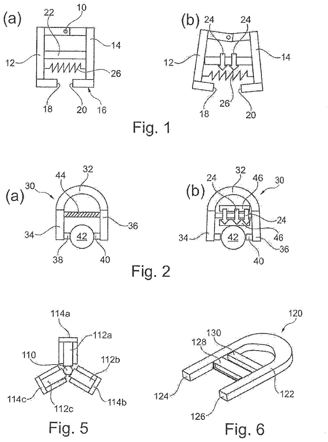
[0027]Possible basic configurations of the present invention (not exhaustive with regard to the breadth of variants) are explained with the aid of FIGS. 1 and 2. Thus, a gripper device schematically shown in the first example of embodiment of FIG. 1 has a gripper 16 formed by two gripping arms 12, 14, which are connected to one another such that they can pivot about a joint 10, and which by means of a pair of jaw sections 18 and 20 formed on the free ends of the arms 12, 14 have contact sections for purposes of interaction with a workpiece (not shown in FIG. 1).

[0028]An MSM crystal body 22, which is designed in the elongated manner as shown from an NiMnGa alloy exhibiting a magnetic shape-memory behaviour, connects the arms 12, 14 such that a magnetic field (arrows 24 in FIG. 1(b)) that is introduced transversely to the direction of extension of the actuator element 22 effects an expansion of the MSM crystal along the direction of extension. In the manner shown, this variation in le...


PUM


Abstract

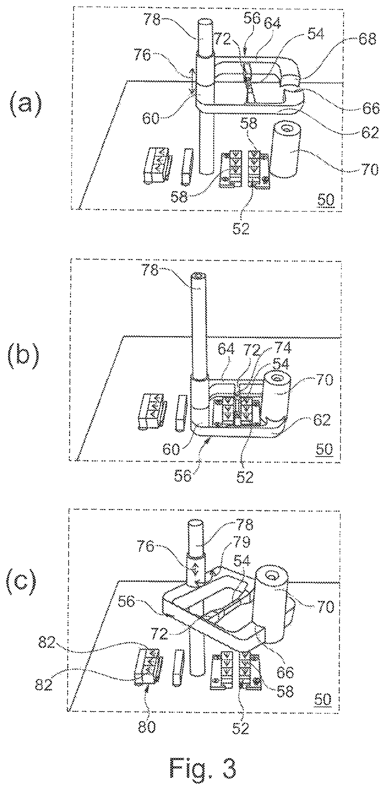
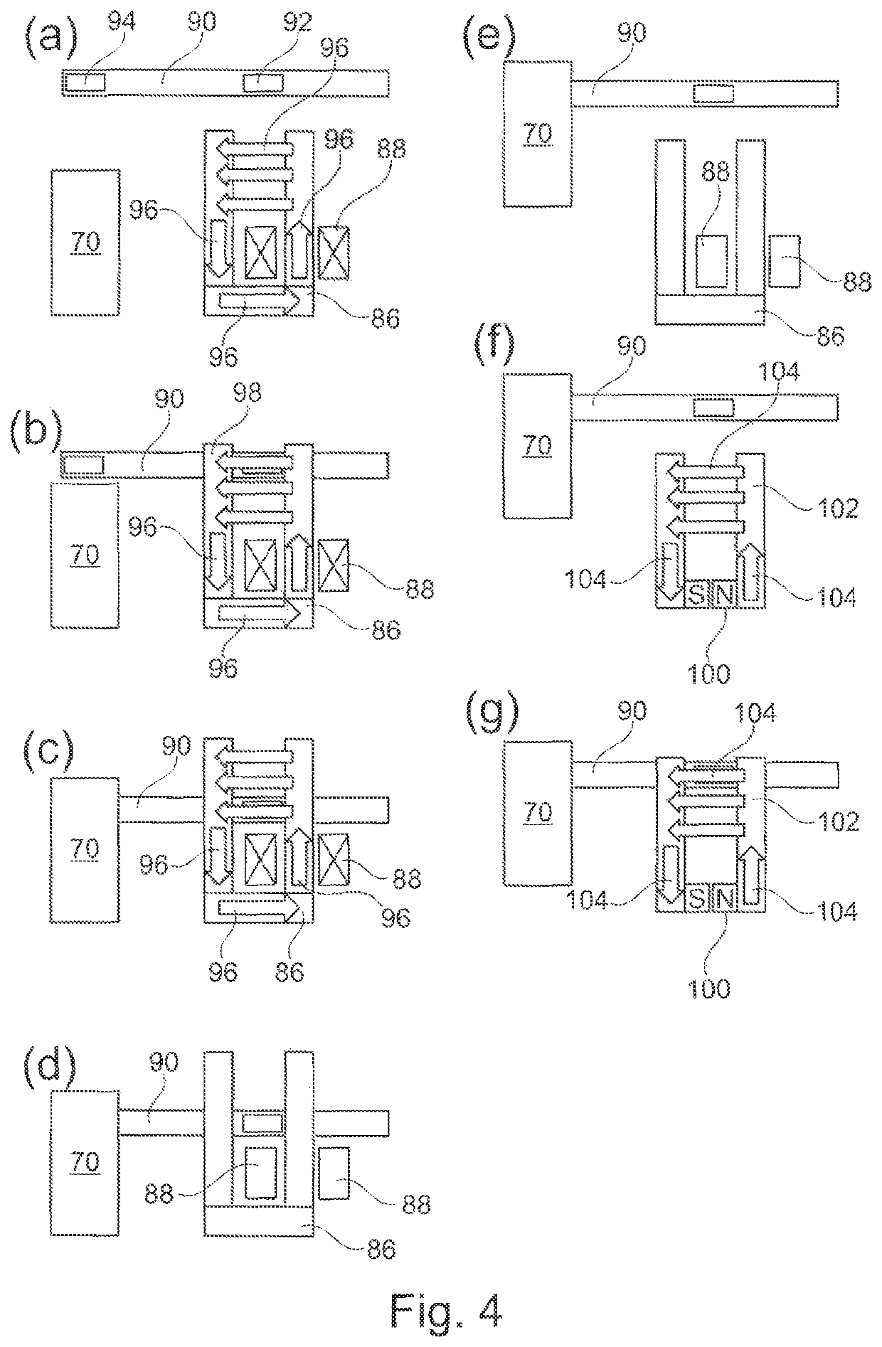
A gripper device (16; 30; 56; 90; 120) which is designed so as to be movable along a movement path, and which serves for grasping and holding a workpiece (70) and for moving the workpiece along the movement path, with at least one first contact section (18; 38; 66) which, to produce an operative pairing with the workpiece that effects the gripping or holding action, can be driven relative to a second contact section (20; 40; 68), which first contact section is assigned actuator means (22; 44; 54; 128), which are designed to exert a drive force in reaction to the application of a magnetic field, and which are composed of a magnetic shape-memory alloy material, wherein the actuator means for magnetic interaction are formed, for the application of a magnetic field, with magnetic field generating means that are static at one position of the movement path (52; 80; 86; 88), and / or with magnetic field generating means that are provided so as to be movable independently of the gripper device.

Description

BACKGROUND OF THE INVENTION[0001]The present invention relates to a gripper device, which is designed so as to be movable along a movement path, and to serve the purpose of grasping and holding a workpiece, and of moving the workpiece along the movement path, in accordance with the preamble of the main claim. The present invention also relates to the utilisation of such a gripper device.[0002]Generic gripper devices are generally of known art in the technical fields of robotics, factory automation and material handling. With the purpose of gripping a wide variety of workpieces for movement purposes at a first position on a movement path, and then passing them on to a different second position of the movement path, generic gripper devices are typically implemented as operative elements in terms of arms or jaws designed for gripping purposes, which, in reaction to a (typically pneumatic or electromagnetic) drive enter into an operative pairing with the workpiece (effecting, for exampl...

Claims


Application Information

Patent Timeline
Patent Type & Authority Patents(United States)
IPC IPC(8): B25J15/02B25J9/10F03G7/06H01L41/12H10N35/00
CPCB25J9/1085F03G7/065B25J15/0246H01L41/12H10N35/00
Inventor SCHIEPP, THOMASLAUFENBERG, MARKUSRAAB, MARKUSERNST, BERNHARD
Owner ETO MAGNETIC GMBH
Learn More