
Apparatus and Methods for Direct Sensing of Rotational Dynamics of a Rotating Shaft

a technology of rotating shafts and apparatuses, applied in the field of telemetry systems, can solve the problems of high-cycle fatigue damage in highly stressed rotor elements, vibration response of the entire shaft train of turbine generators, and cost-effective deployment of this technology in a commercial power plant environmen

Inactive Publication Date: 2017-05-25
ELECTRIC POWER RES INST INC
View PDF13 Cites 4 Cited by
  • Summary
  • Abstract
  • Description
  • Claims
  • Application Information

AI Technical Summary

Benefits of technology

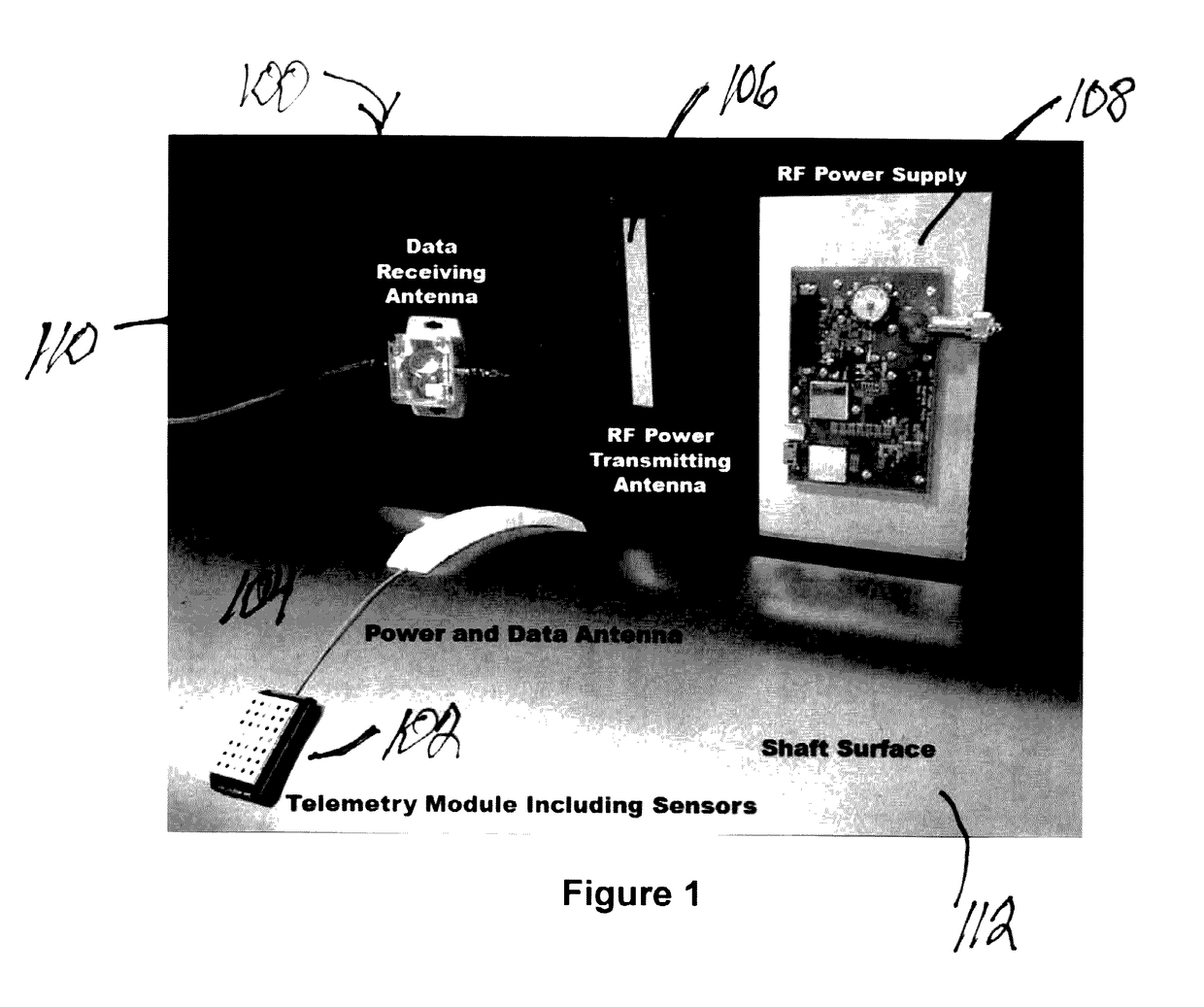
The present invention is a telemetry system for monitoring, measuring, or collecting rotordynamic data from a rotating shaft. The system includes a housing that can have multiple sensors that measure various aspects of shaft rotordynamics in parallel. The system uses radio frequency waves to power and transmit data collected by the sensors, providing a means for monitoring and analyzing the shaft's behavior in real-time. The technology can be applied to a variety of high-speed shafts used in power generation, propulsion, and process plants, and provides a single housing that can include multiple sensors to measure different aspects of shaft rotordynamics. Overall, the invention allows for better monitoring and analysis of rotating shafts, leading to improved efficiency and reliability.

Problems solved by technology

These currents can be grid-induced or caused by unbalanced electrical shorts in the windings.
The resulting torsional stimulus is applied to the generator rotor at twice the line frequency and can result in vibratory response of the entire turbine generator shaft train.
If undetected, the resulting torsional vibration can lead to accumulation of high-cycle fatigue damage in highly stressed rotor elements, such as turbine blades, couplings, exciter shafts, and retaining rings.
While the effect of changes in natural frequencies for an upgrade could be evaluated using rotordynamic models, uncertainty in the model prediction requires the imposition of a wide frequency “avoidance” band surrounding the twice-line-frequency excitation.
Furthermore, these systems, once installed, are often used for torsional testing over limited time durations, typically a few days—not long-term monitoring applications.
Accordingly, the practical difficulties in cost-effective deployment of this technology in a commercial power plant environment has limited its widespread use.

Method used


Image

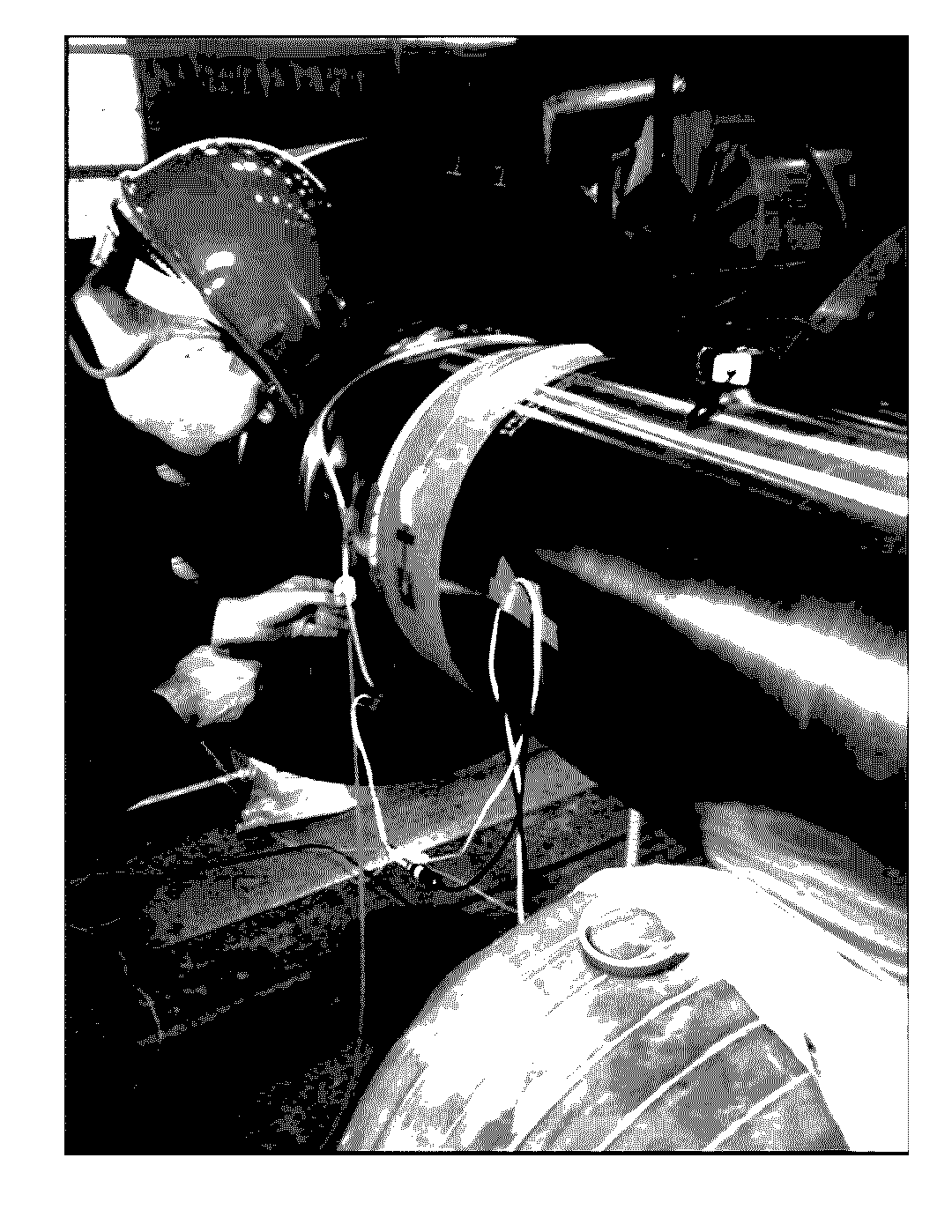
  • Apparatus and Methods for Direct Sensing of Rotational Dynamics of a Rotating Shaft
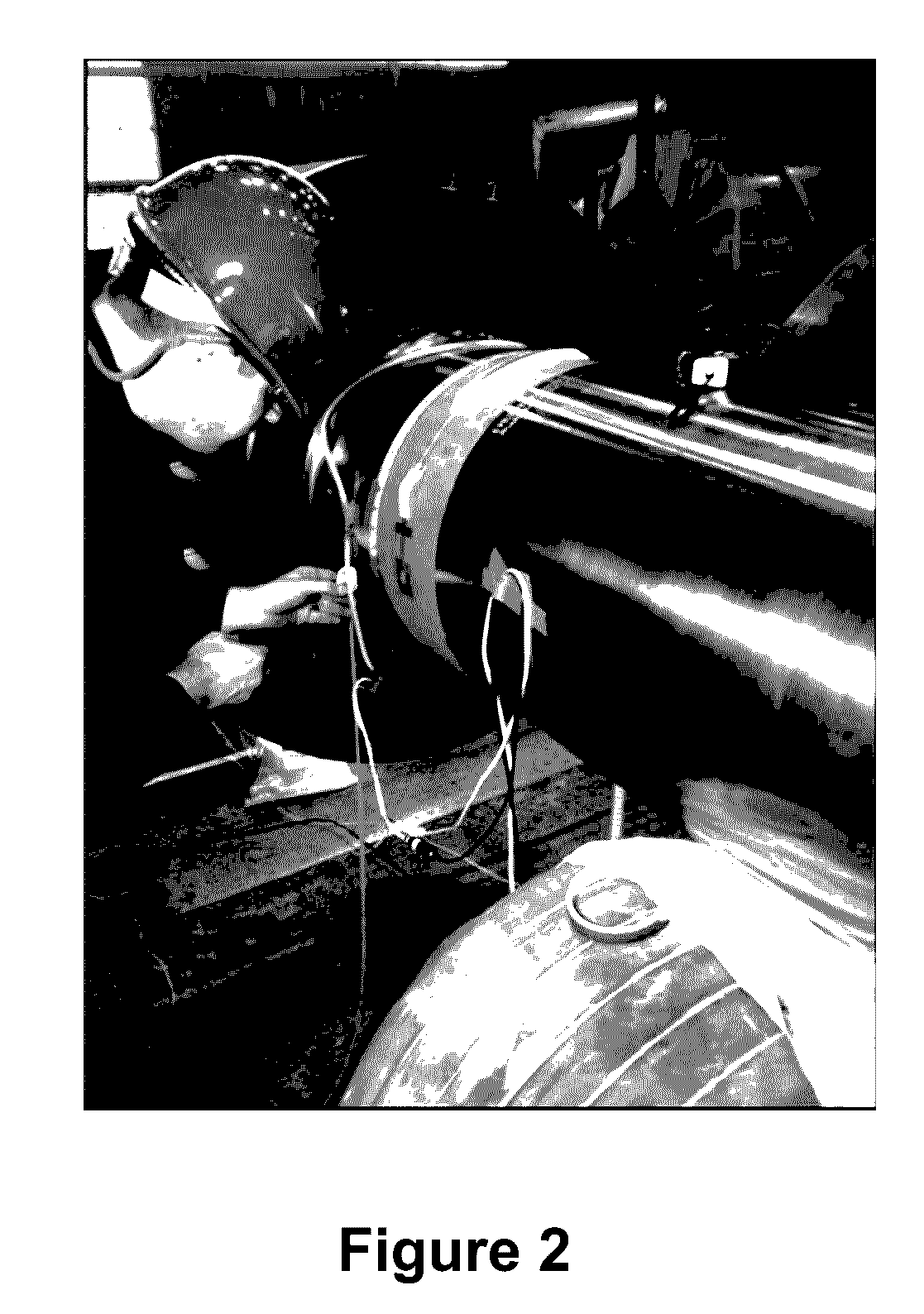
  • Apparatus and Methods for Direct Sensing of Rotational Dynamics of a Rotating Shaft
  • Apparatus and Methods for Direct Sensing of Rotational Dynamics of a Rotating Shaft

Examples


Embodiment Construction

[0024]The present invention is more fully described below with reference to the accompanying figures. While the invention will be described in conjunction with particular embodiments, it should be understood that the invention can be applied to a wide variety of applications, and it is intended to cover alternatives, modifications, and equivalents within the spirit and scope of the invention. Accordingly, the following description is exemplary in that several embodiments are described (e.g., by use of the terms “preferably,”“for example,” or “in one embodiment”), but this description should not be viewed as limiting or as setting forth the only embodiments of the invention, as the invention encompasses other embodiments not specifically recited in this description. Further, the use of the terms “invention,”“present invention,”“embodiment,” and similar terms throughout this description are used broadly and are not intended to mean that the invention requires, or is limited to, any pa...


PUM


Abstract

The invention and its various embodiments are directed to a telemetry system for measuring rotordynamic data from a rotating shaft of interest and methods for using the same. The invention provides a single housing that can include multiple, different sensors that measure various rotordynamic parameters, such as both strain and acceleration, in parallel. A power and data antenna is electrically attached to the housing and the sensors for receiving radio frequency power to power the sensors and to wirelessly transmit data collected by the sensors. Both the housing and the power and data antenna are attached to a rotating shaft and are encapsulated in a fiber coating.

Description

CROSS-REFERENCE TO RELATED APPLICATIONS[0001]This application claims the benefit of provisional Application No. 62 / 259,609, filed Nov. 24, 2015. The entirety of the foregoing application is incorporated by reference herein.BACKGROUND OF THE INVENTION[0002]Field of the Invention[0003]The invention and its various embodiments are directed to an apparatus, system, and method for measuring natural frequencies of rotating shafts. In particular, the invention and its various embodiments are directed to a telemetry system that includes a single, compact telemetry module attached to a rotating shaft, such as a steam turbine generator shaft, to monitor various rotordynamic data using multiple, different sensors within the module; a radio frequency power transmitting antenna connected to a radio frequency power supply to wirelessly provide power to the telemetry module; and a data receiving antenna for wirelessly receiving the rotordynamic data from the telemetry module.[0004]Description of R...

Claims


Application Information

Patent Timeline
Patent Type & Authority Applications(United States)
IPC IPC(8): F01D21/00H04Q9/00
CPCF05D2220/31F05D2240/60H04Q9/00H04Q2209/40F01D21/003H04B17/00G01M13/02Y02T50/60
Inventor HESLER, STEPHENSUPROCK, CHRISTOPHER
Owner ELECTRIC POWER RES INST INC
Learn More