A fluid actuator arrangement

a technology of actuator and fluid, applied in the direction of power amplification, servomotor, transportation and packaging, etc., can solve the problems of high energy cost, ineffective current arrangement, waste of energy through heat dissipation, etc., and achieve the effect of quick pressurization and/or depressurization of the cavity of the membran

Inactive Publication Date: 2017-05-25
SAAB AB
View PDF3 Cites 9 Cited by
  • Summary
  • Abstract
  • Description
  • Claims
  • Application Information

AI Technical Summary

Benefits of technology

[0157]There is thus not needed any additional fluid system or additional fluid controlled mechanical arrangement for providing an engagement of the

Problems solved by technology

This may imply overweight and over-dimension materials, which for a specific operating mode may be regarded as superfluous.
Such centrally controlle

Method used


Image

  • A fluid actuator arrangement
  • A fluid actuator arrangement
  • A fluid actuator arrangement

Examples


Embodiment Construction

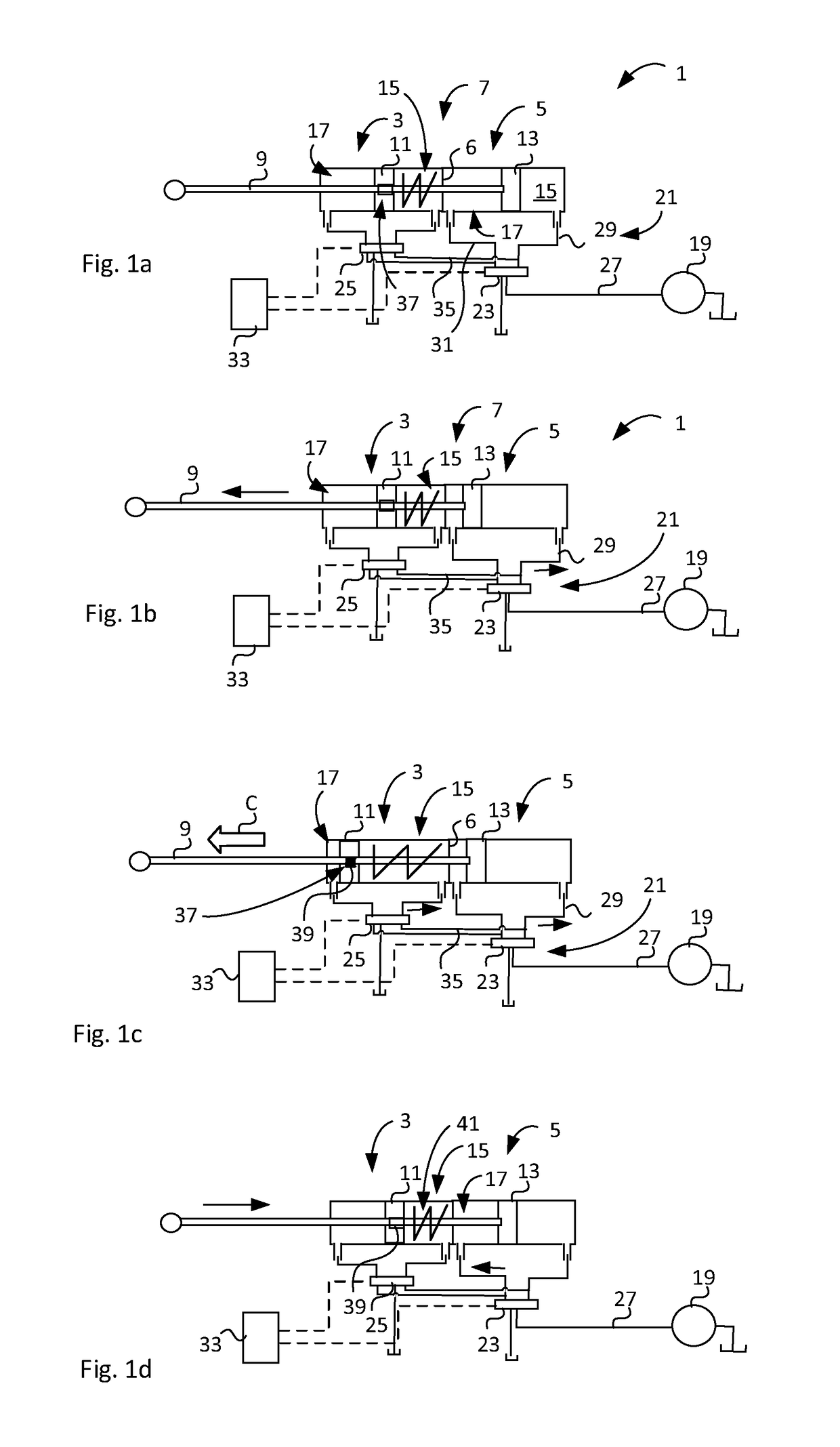
[0192]Hereinafter, embodiments of the present invention will be described in detail with reference to the accompanying drawings, wherein for the sake of clarity and understanding of the invention some details of no importance may be deleted from the drawings.

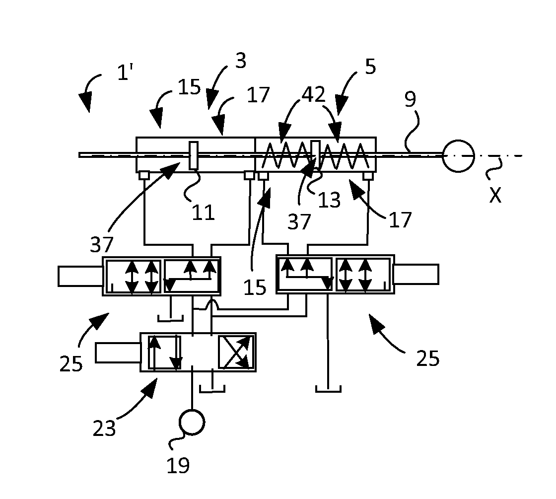
[0193]FIG. 1a schematically shows a fluid actuator arrangement 1 comprising a first 3 and second 5 cylinder of a cylinder arrangement 7. The first 3 and second 5 cylinders are arranged in tandem and rigidly fit to each other by using a common cylinder housing. A partition wall 6 is provided between the cylinders 3, 5. The arrangement 1 further comprises a common piston rod 9 and a first 11 and second 13 piston, each being coupled to the piston rod 9. The first piston 11 is arranged in the first cylinder 3 and divides the latter into a first 15 and second 17 chamber. The second piston 13 is arranged in the second cylinder 5 and divides it into a first 15 and second 17 chamber and is rigidly connected to the piston rod 9. The resp...


PUM


Abstract

The present invention regards a fluid actuator arrangement comprising a first and second cylinder of a cylinder arrangement, a piston rod arrangement, a first and second piston device associated with the piston rod arrangement, wherein respective first and second piston device divides respective first and second cylinder into a first and second chamber provided for connection to a valve device of a fluid supply device. The first piston device comprises a piston rod engagement and disengagement device, which is adapted to engage or disengage the first piston device to/from the piston rod arrangement. The invention can be put into use for aircraft, such as commercial aircraft designed for long distance flights, for construction industry, jacking systems for oil well drilling and service platforms, agricultural equipment industry, marine industry, crane manufacture industry, and others.

Description

TECHNICAL FIELD[0001]The present invention relates to a fluid actuator arrangement according to the preamble of claim1 and to a method for controlling a fluid actuator arrangement according to claim 16. The invention also regards a data medium storing program comprising a program code, which program when run on a computer executes the method according to claim 16. The invention also regards an apparatus arranged to be infinitely movable according to claim 18.[0002]The present invention concerns the industry using hydraulic and pneumatic actuators for different types of applications and concerns the manufacture industry producing such arrangements.[0003]The invention is not limited thereto, but can also be used for replacing electrical actuator arrangements and can be adapted for application of a wide range of different types industries.BACKGROUND ART[0004]There is a desire to provide a fluid actuator arrangement that can distribute control functionality regarding force and motion ra...

Claims


Application Information

Patent Timeline
IPC IPC(8): F15B11/036F15B15/26B64C13/40F15B15/14
CPCF15B11/0365F15B15/1447F15B15/262F15B2211/455F15B2211/7056F15B2211/72B64C13/40B64C13/504Y02T50/40Y02P80/10
Inventor LANDBERG, MAGNUS
Owner SAAB AB
Why Eureka
Try Eureka