Multifunctional safety valve capable of being used for pressure test

A multi-function, safety valve technology, applied in the field of safety valves, can solve the problems of short detection time and fast detection speed, and achieve the effects of fast replacement speed, reduction of detection time, and convenient and quick connection.

Inactive Publication Date: 2017-03-22
王小东
View PDF10 Cites 0 Cited by
  • Summary
  • Abstract
  • Description
  • Claims
  • Application Information

AI Technical Summary

Problems solved by technology

[0004] The technical problem to be solved by the present invention is that it takes a long time to detect all the safety valves on site. Test one by one in a well-sealed environment, and the detection speed is fast and the detection time is short

Method used


Image

  • Multifunctional safety valve capable of being used for pressure test

Examples


Embodiment 1

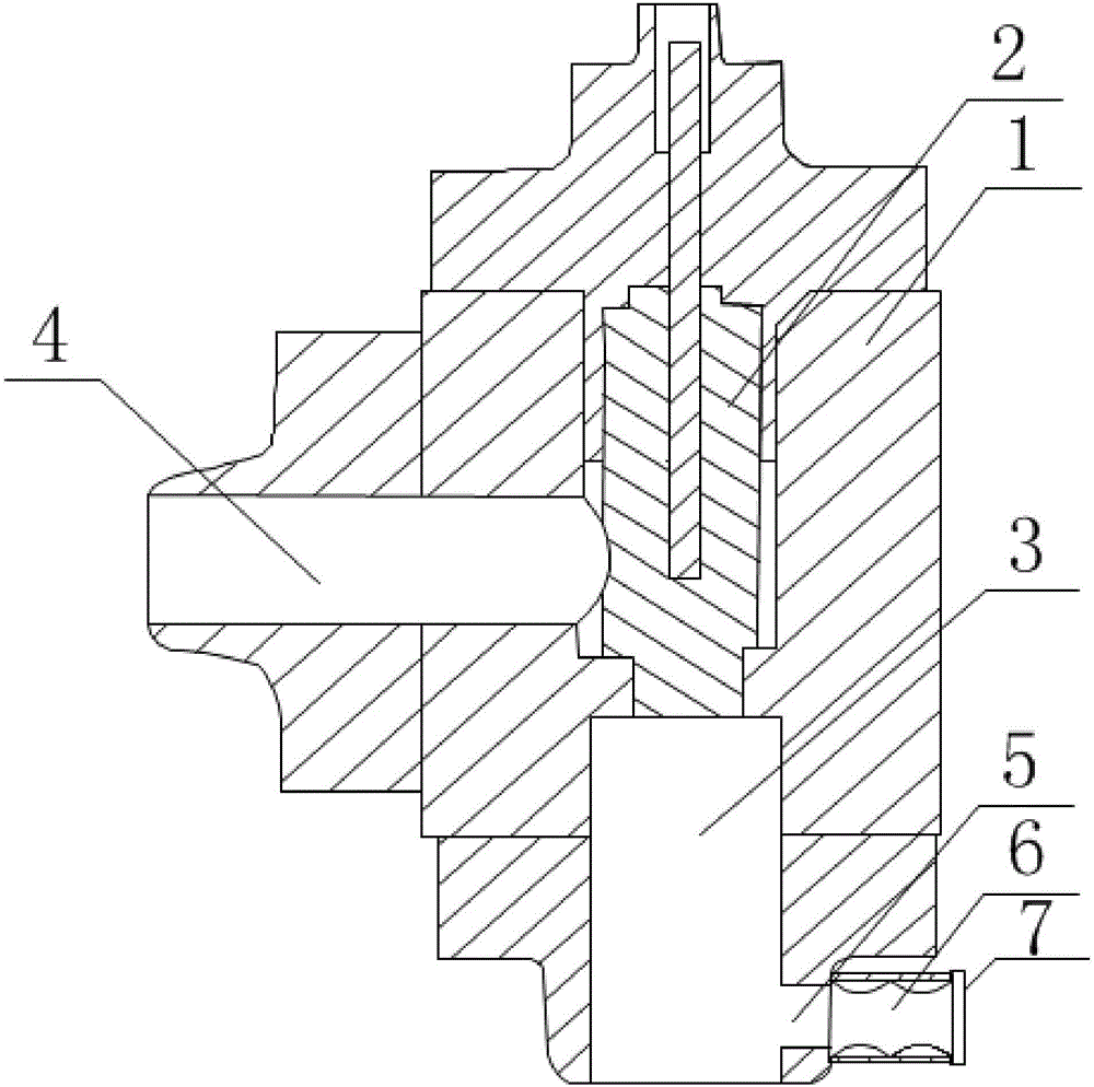
[0025] Such as figure 1 As shown, the present invention is a multifunctional safety valve that can be used for pressure detection, including a valve body 1, a valve core 2 is arranged inside the valve body 1, an inlet passage 3 and an exhaust passage 4 are arranged on the valve body 1, and the inlet passage The passage 3 and the exhaust passage 4 are all connected to the area where the valve core 2 is located. It is characterized in that a through hole 5 is also provided on the side wall of the valve body 1, and the through hole 5 is located at the bottom of the valve body 1. The through hole 5 communicates with the air inlet 3. The side wall of the valve body 1 where the through hole 5 is located is opposite to the side wall of the valve body 1 where the exhaust channel 4 is located with respect to the valve core 2 . The through hole 5 is a circular through hole, and the inner surface of the through hole 5 is a smooth curved surface. The inner surface of the through hole 5 ...

Embodiment 2

[0028] Based on Embodiment 1, the outer end of the through hole 5 is connected with a connecting pipe 6 , the connecting pipe 6 is fixed on the outer wall of the valve body 1 and communicates with the through hole 5 , and the connecting pipe 6 is provided with internal threads. An annular sealing ring 7 is connected to the outer end of the connecting pipe 6 , and the inner wall of the sealing ring 7 is tangent to the outer wall of the connecting pipe 6 . The safety valve and the pressurized pipeline are threaded to facilitate the replacement of the safety valve, and after the pressure test of the safety valve, the pipeline can no longer be equipped with pressurized equipment in the transmission medium, which reduces the installation cost of the pressurized equipment; the pressurized equipment and The safety valve is connected through the connecting pipe. The sealing ring is used to seal the connection between the connecting pipe and the pressurized equipment to avoid pressure ...

Embodiment 3

[0030] Based on the above embodiment, a flow meter is installed on one side wall of the through hole 5 . The flow meter is the same as the actual flow of the pressurized equipment, and the actual pressure of the safety valve can be judged through the flow to further judge the quality of the safety valve. A pressure sensor can be installed on the flowmeter, and the pressure sensor can be connected to the computer to realize self-testing of the actual bearing pressure of the safety valve.


PUM


Abstract

The invention discloses a multifunctional safety valve capable of being used for a pressure test. The multifunctional safety valve comprises a valve body. A valve element is arranged in the valve body. An air inlet channel is arranged at the lower end of the valve element. An exhaust channel is arranged on one side wall of the valve body. One end of the exhaust channel is connected to the valve element. A through hole is formed in the side wall of the valve body and located in the bottom of the valve body. The through hole communicates with the air inlet channel. According to the multifunctional safety valve, the hole is formed in the safety valve, direct connection of the safety valve and pressurized equipment is achieved, the test time of the safety valve is shortened, the input cost of enterprises is reduced, and the structure of the safety valve is changed, so that the safety valve not only has the conventional functions, but also has the off-line quick detection function.

Description

technical field [0001] The invention relates to a safety valve, in particular to a multifunctional safety valve which can be used for pressure detection. Background technique [0002] The safety valve is a special valve whose opening and closing parts are in a normally closed state under the action of external force. When the medium pressure in the equipment or pipeline rises above the specified value, it discharges the medium to the outside of the system to prevent the medium pressure in the pipeline or equipment from exceeding the specified value. . Safety valves are automatic valves, mainly used in boilers, pressure vessels and pipelines, to control the pressure not to exceed the specified value, and play an important role in protecting personal safety and equipment operation. Note that the safety valve must be pressure tested before it can be used. [0003] At present, the following problems will occur in the on-site inspection of safety valves: (1) It is difficult to ...

Claims


Application Information

Patent Timeline
IPC IPC(8): F16K37/00F16K27/02F16K51/00
CPCF16K37/00F16K27/02F16K51/00
Inventor 刘文敏王小东
Owner 王小东
Why Eureka
Try Eureka