Multi-phase reactor capable of obtaining constant inductance for each phase

a multi-phase reactor and inductance technology, applied in the direction of inductance, fixed inductance, inductance with magnetic core, etc., can solve the imbalance of line-symmetric three-phase reactors formed of three winding cores, and the difficulty of setting a constant value of inductance for three phases

Active Publication Date: 2017-06-01
FANUC LTD
View PDF8 Cites 21 Cited by
  • Summary
  • Abstract
  • Description
  • Claims
  • Application Information

AI Technical Summary

Benefits of technology

[0015]The multi-phase reactor may further include core fixing members respectively provided between the peripheral portions of adjacent two of the second cores. The core fixing members may be made of a quality of a material different from that of the plu

Problems solved by technology

However, a line-symmetric three-phase reactor formed of three winding cores undergoes the imbalance between a center winding core (winding) and winding cores

Method used


Image

  • Multi-phase reactor capable of obtaining constant inductance for each phase
  • Multi-phase reactor capable of obtaining constant inductance for each phase
  • Multi-phase reactor capable of obtaining constant inductance for each phase

Examples


Embodiment Construction

[0030]Prior to describing the details of examples of a multi-phase reactor according to the present invention, an example of a conventional multi-phase reactor and a problem thereof are firstly described with reference to FIG. 12. FIG. 12 is a view for illustrating an example of a conventional multi-phase reactor, and illustrating an example of a three-phase reactor.

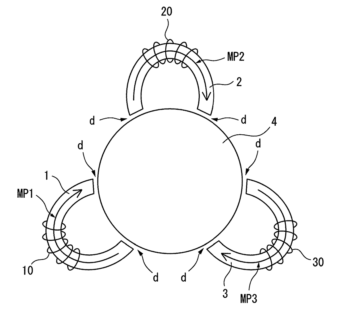
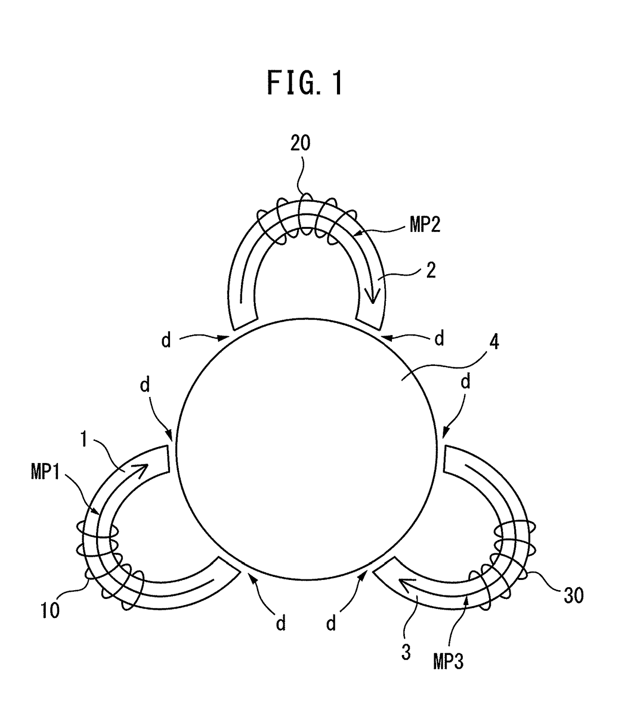
[0031]As illustrated in FIG. 12, the three-phase reactor includes an upper core 104, a lower core 105, and three winding cores 101 to 103 around which windings 110 to 130 for R-phase, S-phase, and T-phase are respectively wound.

[0032]The winding cores 101 to 103 are arranged between the upper core 104 and the lower core 105 with gaps d10 provided respectively. For example, the winding 110 is wound around the winding core 101 for R-phase, the winding 120 is wound around the winding core 102 for S-phase, and the winding 130 is wound around the winding core 103 for T-phase.

[0033]In order to make an inductance constant for e...


PUM


Abstract

A multi-phase reactor is configured to include a first core arranged at a center of the reactor; a plurality of second cores provided outside the first core and arranged so that each of magnetic paths with respect to the first core is in a loop shape; and one or a plurality of windings wound around each of the second cores. With this configuration, the multi-phase reactor capable of setting a constant value of inductance for each phase is provided.

Description

BACKGROUND OF THE INVENTION[0001]1. Field of the Invention[0002]The present invention relates to a multi-phase reactor capable of obtaining a constant inductance for each phase.[0003]2. Description of the Related Art[0004]For example, a three-phase reactor has been conventionally used in an industrial robot, a machine tool, and so on in order to reduce a failure of an inverter and to improve a power factor by being disposed between a power-supply side (primary side) and the inverter or between a load side, such as a motor, (secondary side) and the inverter.[0005]Specifically, a three-phase reactor is disposed on a primary side of an inverter to improve a power factor (for harmonics countermeasure) and to reduce a surge from a power supply. Alternatively, a three-phase reactor is disposed on a secondary side of an inverter to reduce a noise of a motor during operation of an inverter and to take a countermeasure against a surge. A description is given herein of mostly a three-phase re...

Claims


Application Information

Patent Timeline
IPC IPC(8): H01F17/06
CPCH01F17/062H01F3/10H01F27/24H01F37/00H01F3/14
Inventor MAEDA, TAKUYASHIROUZU, MASATOMO
Owner FANUC LTD
Why Eureka
Try Eureka