
Method for manufacturing TFT substrate and TFT substrate manufactured thereof

a manufacturing method and substrate technology, applied in the field of display technology, can solve the problems of poor drive capacity, achieve the effects of reducing off-current to curb warping effect, strong control of the groove, and increasing the open current of the thin film transistor

Active Publication Date: 2017-06-01
SHENZHEN CHINA STAR OPTOELECTRONICS TECH CO LTD
View PDF4 Cites 9 Cited by
  • Summary
  • Abstract
  • Description
  • Claims
  • Application Information

AI Technical Summary

Benefits of technology

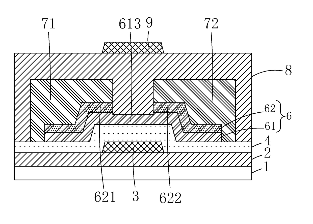
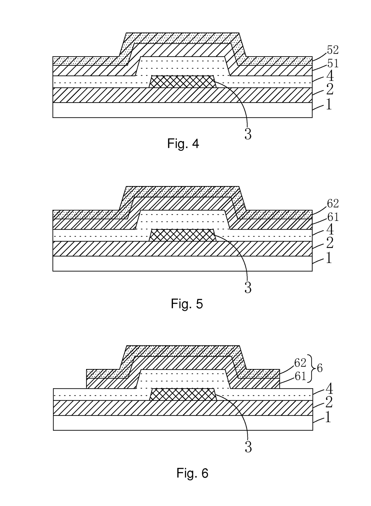
The invention provides a method for manufacturing a TFT substrate using solid phase crystallization, which is a more cost-effective and identical process compared to excimer laser crystallization technology. The double layered structure of the TFT substrate reduces warping effect, leakage phenomenon caused by groove light, and increases the capacity of driving thin film transistors while improving the performance of the TFT substrate. The low temperature poly-silicon layer produced by solid phase crystallization helps to decrease the threshold voltage and slope of subthreshold, and the top grid also acts as a shield insulating light to reduce leakage phenomena caused by groove light. The resulted TFT substrate has better electrical characteristics and capacity of drive with low cost.

Problems solved by technology

The fact encountered currently is that low temperature poly-silicon thin film transistors produced by the method ELA are not identity and over budget, the method SPC can decrease costs and increase identity, but open current and slope of subthreshold are defeated by low temperature poly-silicon thin film transistors produced by ELA, and off-current is big, because of which the drive capacity is poor.

Method used


Image

  • Method for manufacturing TFT substrate and TFT substrate manufactured thereof
  • Method for manufacturing TFT substrate and TFT substrate manufactured thereof
  • Method for manufacturing TFT substrate and TFT substrate manufactured thereof

Examples


Embodiment Construction

[0049]By the following detailed description with reference to accompanying drawings, other aspects and features of the invention will become apparent.

[0050]The invention first provides a method for manufacturing a TFT substrate, including the following sequence:

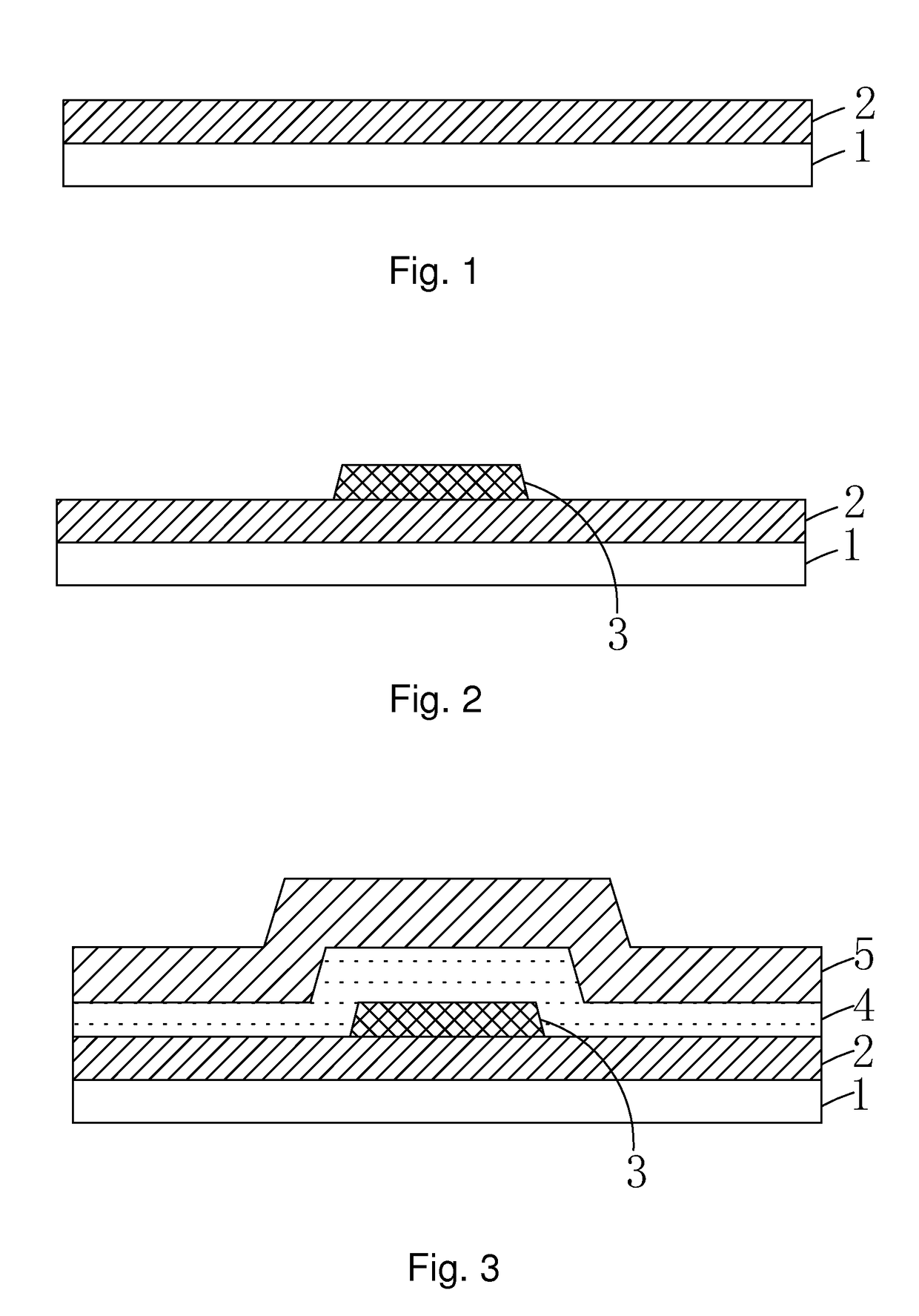
[0051]Step 1, as shown in FIG. 1, providing a substrate 1, after cleansing and pre-toasting the substrate 1, depositing a buffering layer 2 on the substrate 1;

[0052]Specifically, the substrate 1 can be a glass substrate.

[0053]Specifically, the buffering layer 2 can be a single layered structure consisting of silicon nitride, a single layered structure consisting of silicon oxide or a double layered structure consisting of a silicon nitride layer and a silicon oxide layer. Preferably, thickness of the buffering layer 2 can be 500˜2000 A.

[0054]Step 2, as shown in FIG. 2, depositing a first metal layer on the buffering layer 2, and patterning the first metal layer to achieve a bottom grid 3;

[0055]Specifically, the bottom grid 3 ...


PUM


Abstract

The invention provides a method for manufacturing a TFT substrate and a TFT substrate manufactured thereof. In the above TFT substrate, the low temperature poly-silicon layer is produced by solid phase crystallization, the cost of production is under budget, and the TFT substrate is a double-grid structure that can guarantee the electrical characteristics of the thin film transistor and better the capacity of drive, and leakage phenomenon caused by groove light seldom happens.

Description

BACKGROUND[0001]1. Technical Field[0002]The invention relates to the field of display technology, and more particularly to a method for manufacturing a TFT substrate and a TFT substrate manufactured thereof.[0003]2. Description of the Related Art[0004]With the enhancement of tablet display technology, requirements of panels with high resolution and low energy consumption are rising. Due to electronic mobility is high, much attention has been devoted to low temperature poly-silicon (LTPS) in realms of liquid crystal display (LCD) and organic light emitting diode (OLED), LTPS is regarded as a critical material for realizing a full-color tablet display with a small budget. To tablets, a low temperature poly-silicon material takes advantage of high resolution, rapid response time, highlight, high aperture opening ratio, low energy consumption, and a low temperature poly-silicon can be manufactured at low temperatures, and regarded as a subject of extensive study for using in producing a...

Claims


Application Information

Patent Timeline
IPC IPC(8): H01L21/02H01L27/12H01L29/786H01L29/66H01L21/265
CPCH01L21/02667H01L29/66765H01L21/26513H01L29/78633H01L21/02592H01L27/1222H01L29/78618H01L21/02532H01L29/78678H01L27/1237H01L27/1285H01L29/42384H01L29/78648
Inventor ZHOU, XINGYUWU, YUANCHUN
Owner SHENZHEN CHINA STAR OPTOELECTRONICS TECH CO LTD
Learn More