Electric power tool with vibration mechanism

Active Publication Date: 2017-06-08
MAKITA CORP
View PDF0 Cites 18 Cited by
  • Summary
  • Abstract
  • Description
  • Claims
  • Application Information

AI Technical Summary

Benefits of technology

[0022]The engaging depressed portion is disposing on the outer periphery of the stop member. Therefore, the length in the axial direction is reduced in a state where the click sound generating function is maintained.
[0023]The stop member is disposed to restrict the movement of the bearing to the front side in a state of being installed on the tubular portion to realize a rationa

Problems solved by technology

Then, in a case where the vibration driver drill is dropped or the like, an impact from the outside is directly transmitted to the gear case, which may result in damages on the gear case such as cracking f

Method used


Image

  • Electric power tool with vibration mechanism
  • Electric power tool with vibration mechanism
  • Electric power tool with vibration mechanism

Examples


Example

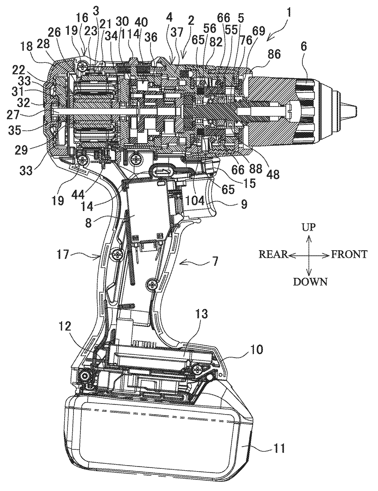
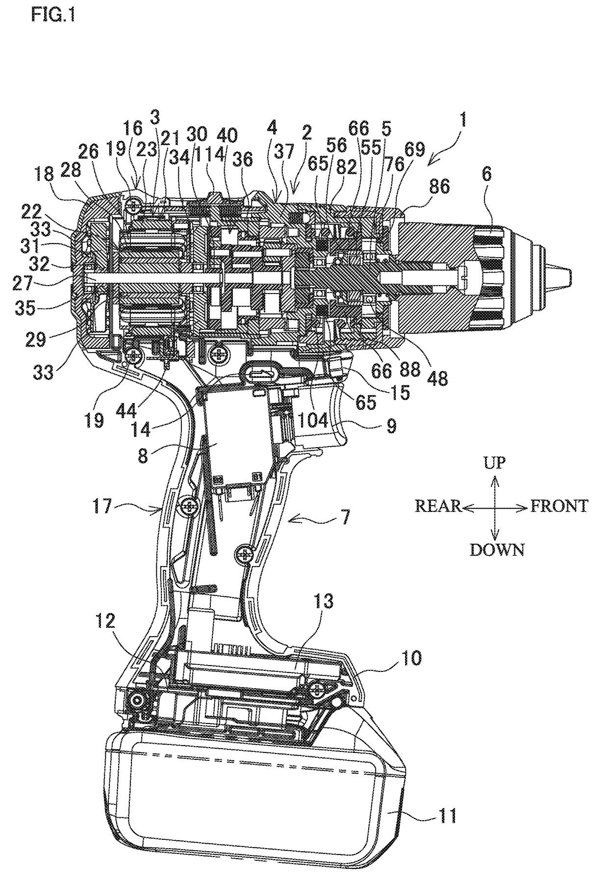
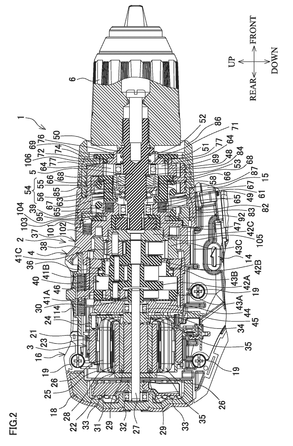
[0033]The following describes embodiments of the disclosure based on the drawings. FIG. 1 is a vertical cross-sectional view of a vibration driver drill as an exemplary electric power tool with vibration mechanism, and FIG. 2 is an enlarged view of a main body. The vibration driver drill 1 includes a main body 2 extending in a front-rear direction, and the main body 2 houses a brushless motor 3 in the rear. The vibration driver drill 1 transmits a torque from the brushless motor 3 to a spindle 5 as a final output shaft projecting forward from a gear assembly 4, which is assembled ahead of the brushless motor 3, via the gear assembly 4. The vibration driver drill 1 includes a drill chuck 6 configured to grip a bit on a distal end on a front end of the spindle 5.

[0034]On a lower side of the main body 2, a handlebar 7 is downwardly disposed. The handlebar 7 internally includes a switch 8 and a battery mounting portion 10. The switch 8 that has a trigger 9 projecting forward is disposed...


PUM

PropertyMeasurementUnit
Diameteraaaaaaaaaa
Torqueaaaaaaaaaa
Expansion enthalpyaaaaaaaaaa

Abstract

An electric power tool includes a housing, a motor, a deceleration mechanism, a final output shaft, a vibration mechanism, a vibration switching member, a stop member, and an expansion prevention portion. The vibration mechanism provides a vibration in an axial direction to the final output shaft. The vibration switching member is accommodated in a slit axially disposed on a front end of a tubular portion and moved back and forth in the slit by an operation from outside to switch on and off actuation of the vibration mechanism. The stop member is installed on the front end of the tubular portion to cover the slit. The expansion prevention portion is disposed on the stop member and is brought in contact with an outer periphery of the front end of the tubular portion to prevent the front end of the tubular portion from expanding,

Description

BACKGROUND[0001]This application claims the benefit of Japanese Patent Application Number 2015-236790 filed on Dec. 3, 2015, the entirety of which is incorporated by reference.TECHNICAL FIELD[0002]The disclosure relates to an electric power tool with vibration mechanism, such as a vibration driver drill, selectably having a vibration mode for providing vibration in an axial direction to a final output shaft.RELATED ART[0003]As an electric power tool with vibration mechanism, for example, Japanese Patent Application Publication No. 2005-193361 discloses a vibration driver drill that transmits a torque from a motor to a spindle as a final output shaft via a gear assembly and includes a vibration mechanism configured to select a vibration mode for providing vibration in an axial direction to the spindle. The vibration mechanism includes a gear assembly on which a front gear case is disposed to include two cams externally mounted on the spindle. A first cam is integrally secured to the ...

Claims


Application Information

Patent Timeline
IPC IPC(8): B25B21/02B25F5/00
CPCB25F5/001B25B21/023B25F3/00B25D16/006B25D2211/064B25D2216/0023B25D2216/0038B25F5/00B23B45/00
Inventor NAGASAKA, HIDENORI
Owner MAKITA CORP
Why Eureka
Try Eureka