Plug-in fiber coupling unit, fiber coupling system and method for coupling optical fibers to integrated optical waveguides

Active Publication Date: 2017-06-08
FRAUNHOFER GESELLSCHAFT ZUR FOERDERUNG DER ANGEWANDTEN FORSCHUNG EV
View PDF2 Cites 0 Cited by
  • Summary
  • Abstract
  • Description
  • Claims
  • Application Information

AI Technical Summary

Benefits of technology

The present invention is aimed at providing a method and fiber coupling unit for easily and inexpensively coupling optical fibers to optical waveguides integrated into a substrate, which require minimal adjusting effort during the coupling process. The fiber coupling unit allows for a purely passive mechanical adjustment during the coupling process in three directions (z-direction, x-direction, and y-direction) and can be cost-effectively realized due to the use of glass or polymer materials instead of silicon. It is easy to package and can be fixed on the substrate with the optical waveguides separably or inseparably. The fiber coupling unit makes it easy to couple optical fibers to integrated waveguides in optical substrates, such as circuit boards and modules, with standard plug-type optical fiber interfaces or open-beam interfaces.

Problems solved by technology

However, the considerable tolerances in the manufacture of circuit boards have thus far precluded an industrial application of this technology.
However, the use of a silicon substrate with structures that are very exactly produced by means of conventional silicon etching technologies (for example, anisotropic etching, wet-chemical etching or ion beam etching) is associated with relatively high costs.

Method used


Image

  • Plug-in fiber coupling unit, fiber coupling system and method for coupling optical fibers to integrated optical waveguides
  • Plug-in fiber coupling unit, fiber coupling system and method for coupling optical fibers to integrated optical waveguides
  • Plug-in fiber coupling unit, fiber coupling system and method for coupling optical fibers to integrated optical waveguides

Examples


Embodiment Construction

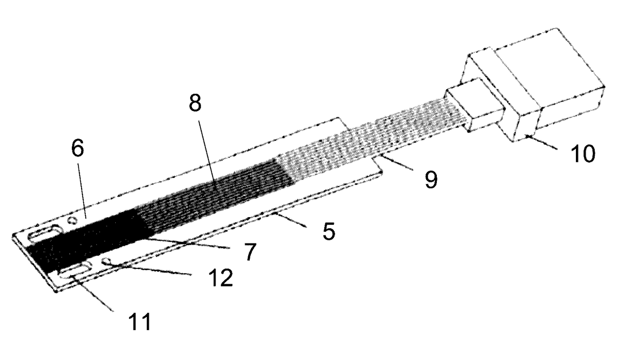
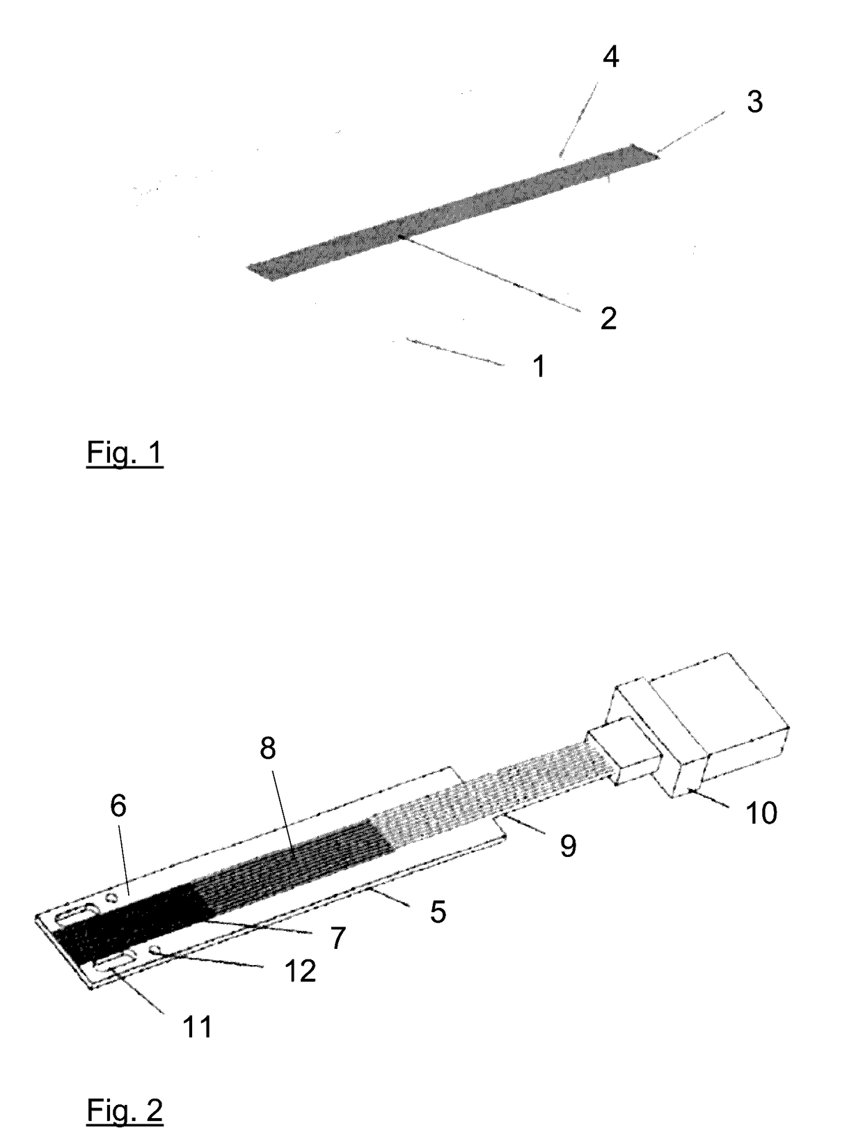
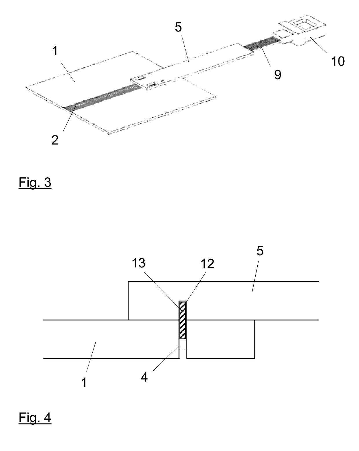
[0025]The proposed method and the proposed fiber coupling unit for coupling optical fibers to an optical glass substrate with integrated optical waveguides are described below. An example of such an optical glass substrate is illustrated in FIG. 1. This figure shows a glass substrate 1 with planar waveguides 2 integrated on the surface thereof. Optical signals can be coupled into the waveguides 2 or optical signals can be decoupled from the waveguides 2 via the end face 3 on the outer edge of the glass substrate 1. Optical fibers for relaying or delivering the optical signals should be coupled to this location. In the present example, two locating bores 4 are produced in the glass substrate 1 and extend through the entire glass substrate in order to realize the passive mechanical adjustment of the fiber coupling unit relative to the glass substrate 1. The cross section of these locating bores 4 corresponds to the cross section of mechanical connecting pins that are inserted into the...


PUM


Abstract

The present invention relates to a method, as well as a fiber coupling unit, for coupling optical fibers to optical waveguides that are integrated into a substrate. The coupling unit features a contact surface for contacting the surface of the substrate with the integrated waveguides, as well as trench structures for accommodating optical fibers. The end faces of inserted fibers and / or a raised structure on the edge of the contact surface form a coupling or stopping face for the end face of the substrate with the integrated waveguides. At least one opening is produced in the contact surface and designed for accommodating a mechanical connecting element in a form-fitting fashion or guiding a mechanical connecting element parallel to the contact surface and perpendicular to the coupling or stopping face in a form-fitting fashion. Alternatively, the contact surface may also be rigidly connected to a connecting element protruding from the contact surface. The proposed method and the proposed fiber coupling unit, the coupling substrate of which consists of a glass or polymer material, make it possible to cost-effectively realize the coupling of optical glass fibers to integrated waveguides with minimal effort.

Description

CROSS-REFERENCE TO RELATED APPLICATION[0001]This application claims priority to Application No. 10 2015 224 397.4 filed in Germany on Dec. 7, 2015, the disclosure of which is incorporated herein by reference in its entirety.BACKGROUND OF THE INVENTION[0002]Technical Field[0003]The present invention relates to a fiber coupling unit, to a method for coupling optical fibers to optical waveguides that are integrated into a substrate and extend up to an end face of the substrate, as well as to a fiber coupling system consisting of the fiber coupling unit and the substrate with the integrated waveguides.[0004]Optical glass substrates with planar integrated waveguides require a plurality of optical interfaces for incoupling and outcoupling the optical signals. For this purpose, the integrated waveguides frequently have to be coupled to optical fibers, by means of which the optical signals are transported to and from the optical glass substrate. The coupling of the optical fibers requires a...

Claims


Application Information

Patent Timeline
IPC IPC(8): G02B6/30G02B6/122G02B6/136G02B6/38
CPCG02B6/30G02B6/136G02B6/122G02B6/3881
Inventor BRUSBERG, LARSSCHROEDER, HENNING
Owner FRAUNHOFER GESELLSCHAFT ZUR FOERDERUNG DER ANGEWANDTEN FORSCHUNG EV
Why Eureka
Try Eureka