Board connector
a board connector and connector technology, applied in the direction of line/current collector details, coupling device connections, electrical apparatus, etc., can solve the problems of poor solder wettability and high post-plating cost, and achieve the effect of improving workability, reducing the number of components, and improving the wettability of the solder
- Summary
- Abstract
- Description
- Claims
- Application Information
AI Technical Summary
Benefits of technology
Problems solved by technology
Method used
Image
Examples
first embodiment
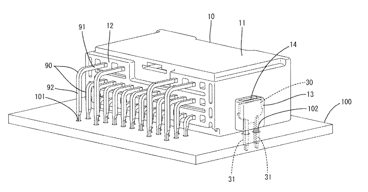
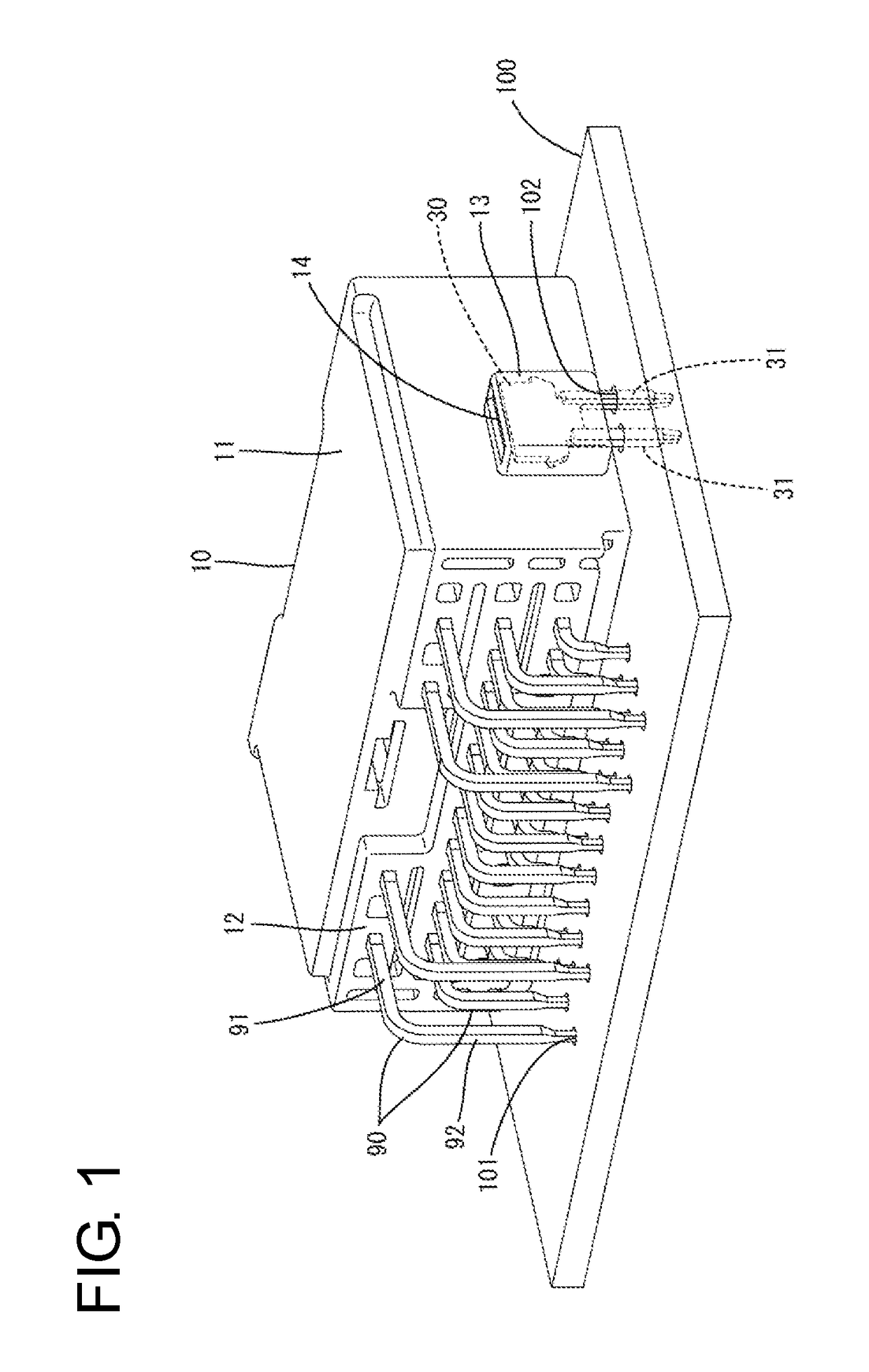
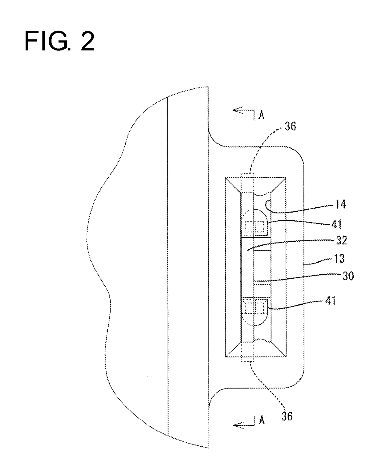
[0039]As shown in FIGS. 3 and 4, the board fixing portion 31 has a tip area 37 projecting on the underside of the circuit board 100 in a state inserted in the fixing hole 102. The board fixing portion 31 includes first and second plate pieces 38A, 38B facing each other in a plate thickness direction PTD (lateral direction in the case of the first embodiment).
[0040]The plate pieces 38A, 38B are formed over the entire width of the board fixing portion 31 in a plate width direction PWD (front-back direction) and over the entire length thereof in a vertical length direction LD, and are continuous with front and rear ends of the lower portion 34 of the housing fixing portion 32.
[0041]The plate pieces 38A, 38B are coupled unitarily via a bend 39 except at the tip area 37. As shown in FIGS. 4, 6 and 10, the coupled plate piece 41 having a U-shaped cross-section is formed by the plate pieces 38A, 38B and the bend 39. The coupled plate piece 41 comprises the first plate piece 38A continuous ...
fourth embodiment
[0064]On the other hand, in the fourth embodiment, a sufficient holding force of the fixing member 30G in a housing 10 can be ensured regardless of a plate thickness of the fixing member 30G.
[0065]As shown in FIG. 15, the fixing member 30G is comprises two long and narrow legs 52 extending in the vertical direction and a bridging portion 53 bridging between the upper ends of the both legs 52. The bridging portion 53 and the legs 52 are in the form of strips wide in a plate thickness direction (lateral direction).
[0066]A housing fixing portion 32G is configured by the bridging portion 53 and upper end parts of the legs 52 and U-shaped in a side view. Two locking projections 36G protrude in the lateral direction on left and right edge parts of the upper or distal end parts of the legs 52. As shown in FIGS. 13 and 14, when the fixing member 30G is inserted into a mounting groove 14G of a mounting portion 13G of the housing 10, the locking projections 36G bite into left and right edges ...
fifth embodiment
[0076] the board fixing portion 31H comprises the two plate pieces 38AH, 38BH. Two plating drip layers 43H are formed on each of the plate pieces 38AH, 38BH, i.e. a total of four plating drip layers 43H are formed, and each plating drip layer 43H can function as a solder adhesion area. Thus, solder wettability can be improved.
PUM
 Abstract
Description
Claims
Application Information
 - R&D
- Intellectual Property
- Life Sciences
- Materials
- Tech Scout
- Unparalleled Data Quality
- Higher Quality Content
- 60% Fewer Hallucinations
Browse by: Latest US Patents, China's latest patents, Technical Efficacy Thesaurus, Application Domain, Technology Topic, Popular Technical Reports.
© 2025 PatSnap. All rights reserved.Legal|Privacy policy|Modern Slavery Act Transparency Statement|Sitemap|About US| Contact US: help@patsnap.com


