Communication control method and mobile terminal

a communication control and mobile terminal technology, applied in the field of new devices, can solve the problems of reachability of communication, efficiency of communication, etc., and achieve the effect of maximizing the spread speed of relay transfer, scalability of communication capacity, and maximizing the spread efficiency of relay transfer

Active Publication Date: 2017-06-08
TOHOKU UNIV
View PDF3 Cites 19 Cited by
  • Summary
  • Abstract
  • Description
  • Claims
  • Application Information

AI Technical Summary

Benefits of technology

[0035]As described above, in the present invention, since the existing group is dissolved and reconstructed, and thus a mobile terminal outside the group newly becomes a group fellow with a mobile terminal storing relay data before the dissolution, the relay data is relayed and transferred to the terminal which newly becomes the group fellow within the new group after the reconstruction. Hence, in the present invention, the operation of relaying the transfer data stored within the mobile terminal before the dissolution of the group to the mobile terminal which newly becomes the group fellow from the outside of the group is repeated any number of times by the repeated execution of the dissolution / reconfiguration of the group. Consequently, in the present invention, it is possible to realize the multi-hop communication for relaying and transferring the transfer data even if the upper limit (two hops) of the number of relay hops in the relay system performing terminal-to-terminal communication on an individual terminal group basis is exceeded.
[0036]At that time, for example, since in the present invention, the mobile terminal in which immediately before the dissolution of the group, the number of adjacent node terminals outside the group is the largest is set to the GO for the group after the reconstruction, when seen from the GO, the number of terminals which are newly added to the group fellow from the outside of the group can be maximized after the reconstruction of the group. The adjacent node terminal refers to an adjacent mobile terminal which responds to the adjacent search beacon issued by the present terminal so as to be wirelessly connected as the subsequent hop node to the present terminal. Consequently, in the present invention, in the process in which the dissolution and reconstruction of the group described above are repeated, the efficiency of the spread and the speed of the spread of the stored data in the relay transfer within the group described above can be maximized.
[0037]Consequently, in the present invention, a wide variety of packet relay systems are used together, and thus it is possible to realize a mechanism which can solve the problems in the reachability of the communication, the scalability of the communication capacity, the efficiency of the communication and the optimization of the efficiency of the consumption of terminal power described above.

Problems solved by technology

Even if in the wireless network environment described above, the various packet relay systems described above are appropriately used according to the conditions or are used by being combined, the following problems are still present.
In other words, a problem in the reachability of communication, a problem in the scalability of a communication capacity, a problem in the efficiency of communication and a problem in the optimization of the efficiency of the consumption of power in a terminal caused by the systems are not solved.
(1) In the table drive-type relay system, when the mobility of each mobile terminal is increased, and a wireless channel state between mobile terminals becomes unstable, the topology of the entire network becomes unstable, with the result that a packet arrival failure rate in the End-To-End is rapidly increased.
In other words, in the table drive-type relay transfer system, the End-To-End communication route becomes very unstable.
(2) In the table drive-type relay system, routing information is constantly exchanged between a plurality of mobile terminals, and thus terminal batteries are remarkably consumed or the communication capacity is reduced.
Moreover, in the storage transfer-type packet relay transfer system in which the End-To-End communication route is not determined until the packet reaches the final destination, it is impossible to guarantee the arrival of the packet in the End-To-End regardless of whether or not the communication state is satisfactory.
Specifically, disadvantageously, when a table drive-type relay system is used, as long as a wireless channel state within a wireless network and a radio wave condition are not maintained to be ideal, the period during which the communication route is stably present is shortened, and the probability that the communication route is stably maintained is lowered.
Moreover, disadvantageously, when a storage transfer-type relay system is used, as the number of hops in the End-To-End communication route is increased, the probability that the packet reaches the final destination is lowered, with the result that a communication delay time necessary for the arrival is increased.

Method used


Image

  • Communication control method and mobile terminal
  • Communication control method and mobile terminal
  • Communication control method and mobile terminal

Examples


first example

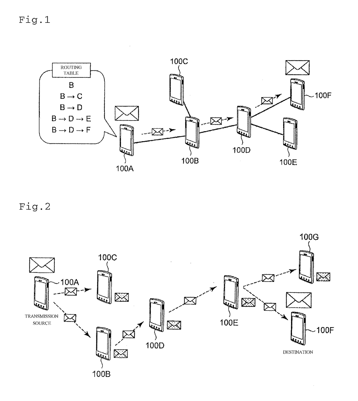
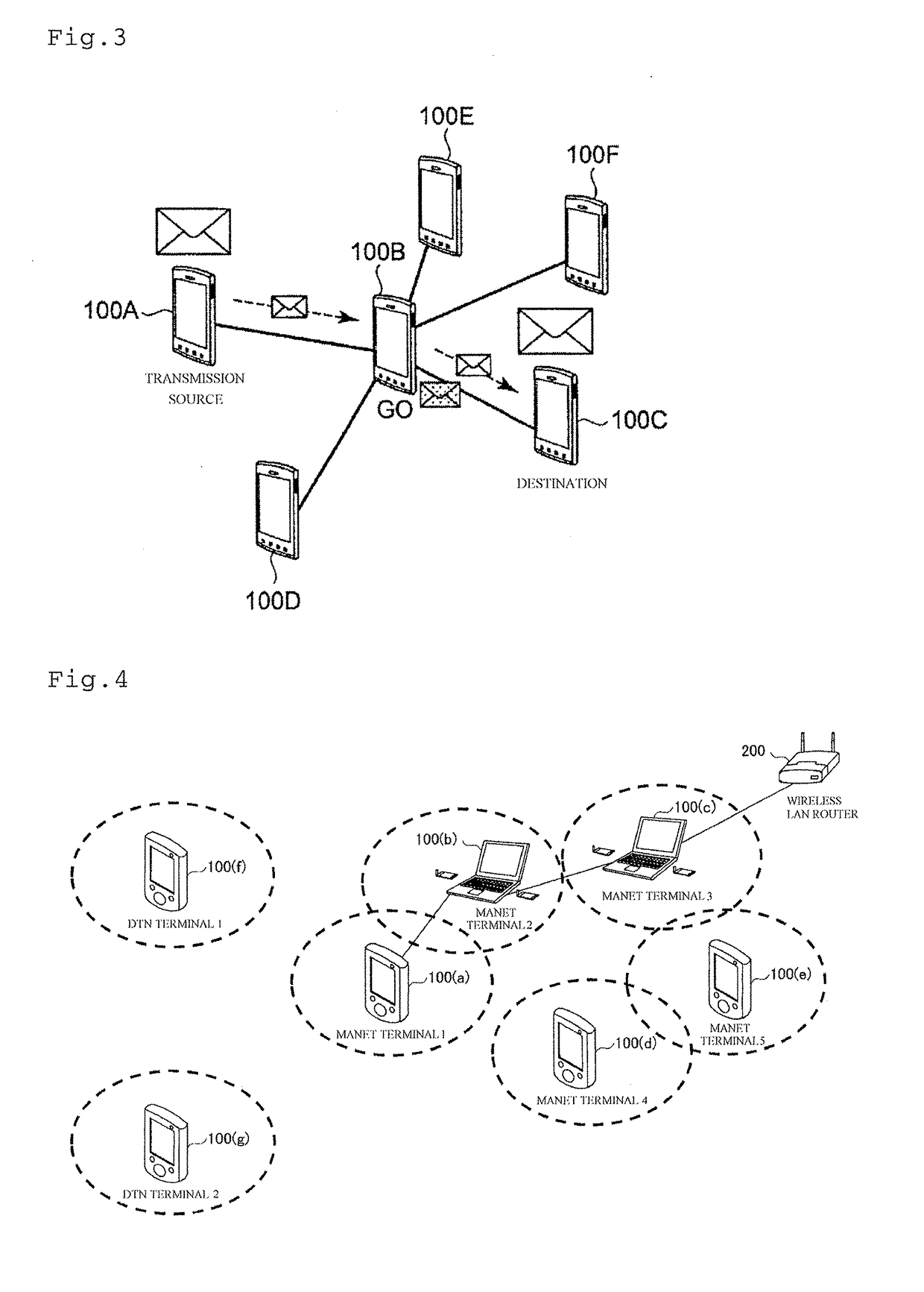
[0161] First Example

[0162]As a result of the selection of the size of the terminal group based on the degree of the stability of the End-To-End communication route up to the parent node terminal serving as the GO in the “relay system based on the terminal group” according to the present embodiment, in any of the terminal groups, the size is constantly one hop. The first example corresponds to this special case. Since in the first example, in any of the terminal groups, the size is constantly one hop, the network connection topology of each terminal group is the star-type network connection topology shown in FIG. 3, and within the terminal group, the packets are relayed and transferred in the “star connection-type packet relay system”.

[0163]In the star-type connection network in which the “star connection-type packet relay system” shown in FIG. 3 is performed, the number of hops capable of relaying the transfer data is restricted to two hops. Hence, the first example discloses a tech...

second example

[0233] Second Example

[0234]A second example will be described below with reference to FIG. 19. In the following description of the second example, the same description as in the first example will be omitted, and only differences from the first example will be described.

[0235]As in the first example, in the second example, after the GO determines that the dissolution and the reconfiguration of the terminal group are performed, the GO which receives the Intent values from all the child node terminals within the terminal group selects, as the subsequent new GO, the child node terminal which transmits the maximum Intent value. Then, the GO transmits, to the selected child node terminal, a selection notification for notifying that the child node terminal is selected as the subsequent new GO, and dissolves the current terminal group. The child node terminal receiving the selection notification starts an operation as the subsequent new GO, and in order to form the subsequent new terminal ...


PUM


Abstract

In a communication control method and a mobile terminal it is possible to realize multi-hop communication having three or more hops in a routing system based on a star-type network connection topology which is more efficient than conventional table drive-type and storage transfer-type routings. An operation of relaying transfer data stored within a mobile terminal before the dissolution of s group to a mobile terminal which newly becomes a group fellow from the outside of the group is repeated any number of times by the repeated execution of the dissolution/reconfiguration of the group. Consequently, it is possible to realize multi-hop communication for relaying and transferring the transfer data even if the upper limit (two hops) of the number of relay hops in a star connection-type system is exceeded.

Description

TECHNICAL FIELD[0001]The present invention relates to a novel packet relay control system between mobile terminals, and more specifically, relates to a communication control method of the packet relay control system which is performed between mobile terminals in order to improve reliability and efficiency when End-To-End communication is performed between mobile terminals without the intervention of a wireless access point and to a mobile terminal.BACKGROUND ART[0002]In recent years, for example, a technology, such as a wireless ad-hoc network, for performing End-To-End communication between mobile terminals without the intervention of a wireless access point has been known. Realization systems which are presently and widely known on packet relay control for performing End-To-End communication between mobile terminals without the intervention of a wireless access point are broadly divided into a “table drive type (see, for example, Non Patent Literatures 1 and 2 below)” and a “stora...

Claims


Application Information

Patent Timeline
Patent Type & Authority Applications(United States)
IPC IPC(8): H04W40/14H04W4/06H04W8/00H04L12/733H04L45/122
CPCH04W40/14H04L45/122H04W84/18H04W8/005H04W88/04H04W4/06H04W28/14
Inventor KATO, NEINISHIYAMA, HIROKI
Owner TOHOKU UNIV
Why Eureka
Try Eureka