Electrical junction box

a junction box and circuit board technology, applied in the direction of fixed connections, electric apparatus casings/cabinets/drawers, transportation and packaging, etc., can solve problems such as troublesome assembly operation, and achieve the effect of simplifying the operation of assembling the plurality of terminals on the circuit board

Inactive Publication Date: 2017-06-08
AUTONETWORKS TECH LTD +2
View PDF13 Cites 3 Cited by
  • Summary
  • Abstract
  • Description
  • Claims
  • Application Information

AI Technical Summary

Benefits of technology

[0022]According to this invention, the operation of assembling the plurality of terminals to the circuit boards can be simplified.

Problems solved by technology

Thus, there is a problem that the assembly operation becomes troublesome.

Method used


Image

  • Electrical junction box
  • Electrical junction box
  • Electrical junction box

Examples


embodiment

[0036]An embodiment is explained with reference to FIGS. 1-3.

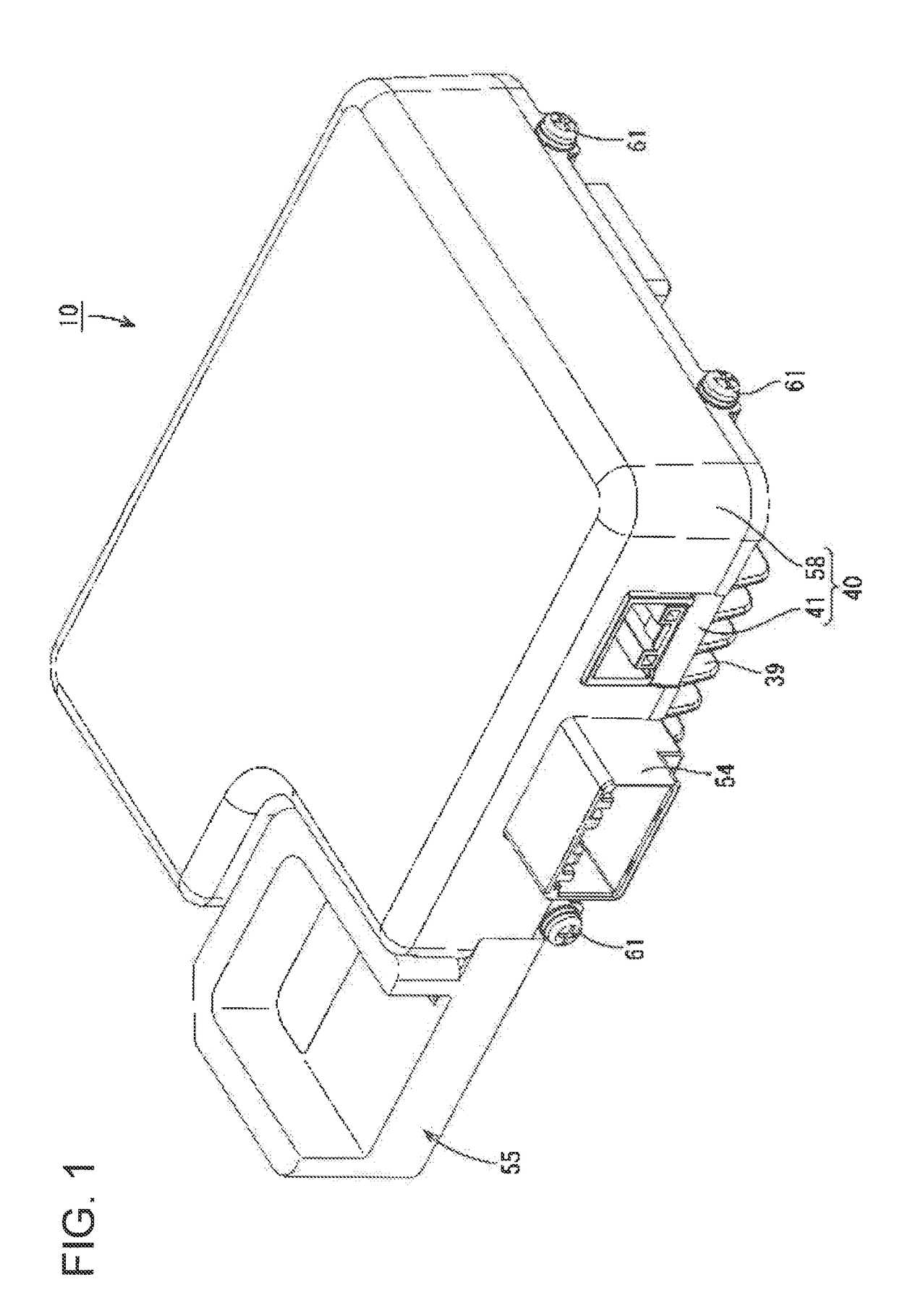
[0037]An electrical junction box 10 is arranged, for example, on a power supply path between (i) a power source such as a battery or the like of a vehicle such as an electric vehicle, a hybrid vehicle, or the like and (ii) a load constituted by an onboard electronic component such as a lamp or the like, a drive motor, or the like and can be used for, for example, a DC-DC converter, an inverter, or the like. Hereafter, for purposes of explanation, the directions of FIG. 6 are used as references for an upward / downward direction (Z axis) and a rightward / leftward direction (Y axis). For a forward / backward direction (X axis), the leftward direction of FIG. 5 is used as a forward direction, and the rightward direction of FIG. 5 is used as a backward direction.

Electrical Junction Box 10

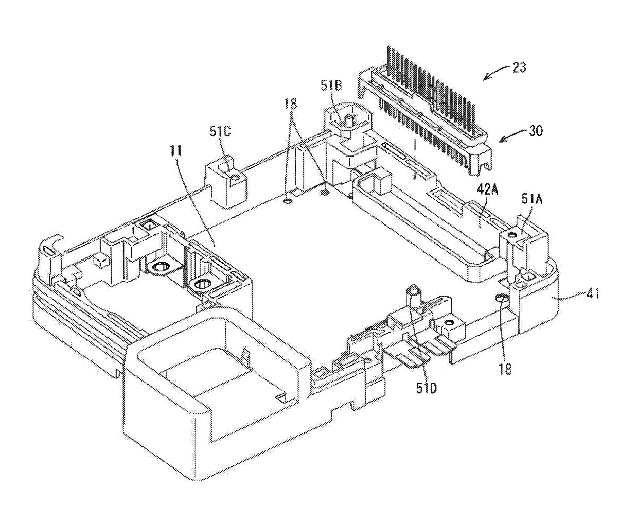
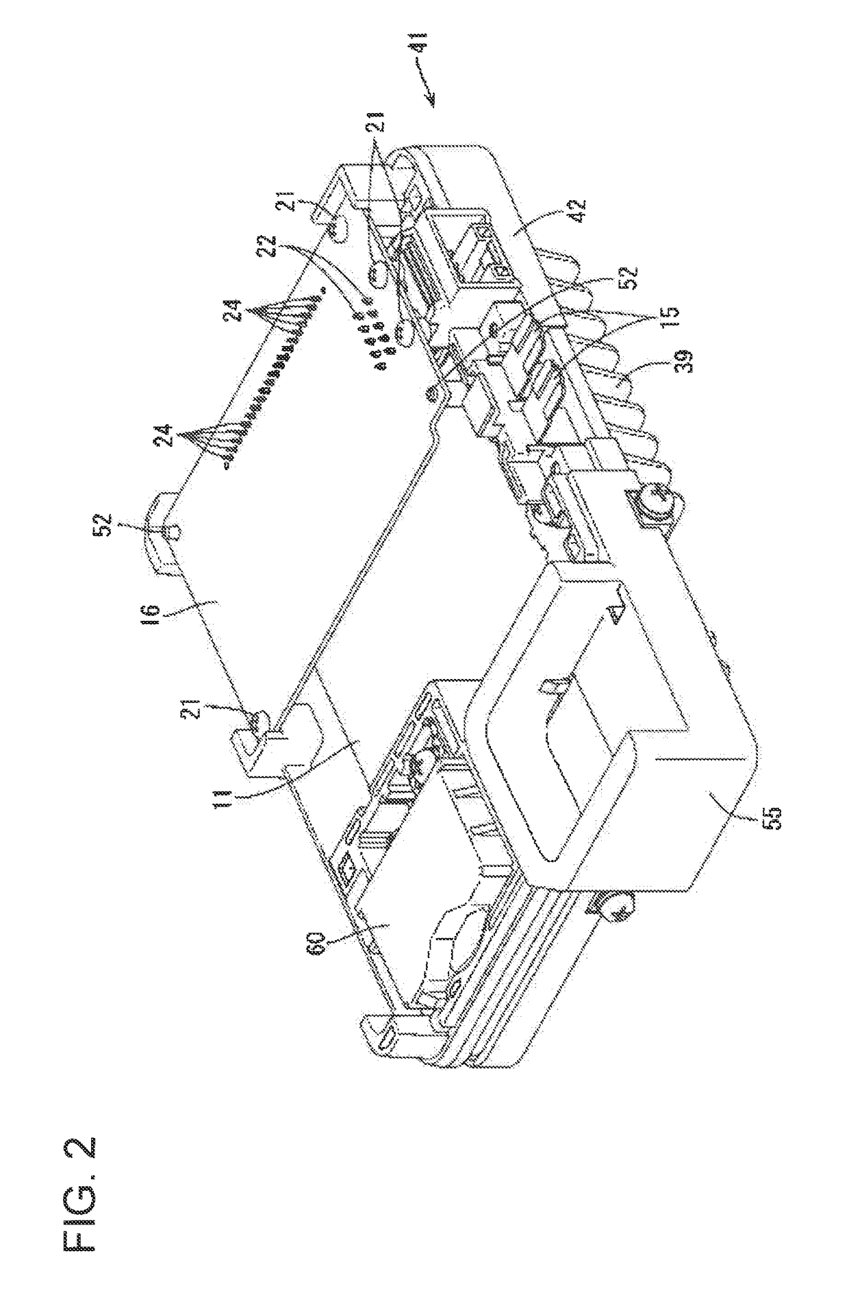
[0038]As shown in FIGS. 1 and 2, the electrical junction box 10 is provided with (i) a first circuit board 11, (ii) a second circuit board 16 that...


PUM


Abstract

An electrical junction box includes a first circuit board that includes electroconductive paths; a second circuit board that includes electroconductive paths; a terminal module including (i) a plurality of terminals that connect the electroconductive paths of the first circuit board and the electroconductive paths of the second circuit board and (ii) an insulative connecting member that connects the plurality of terminals; and a retaining member that retains at least one of the first and second circuit boards. The retaining member has a fitting portion into which the connecting member is fitted.

Description

TECHNICAL FIELD[0001]This invention relates to an electrical junction box.BACKGROUND TECHNOLOGY[0002]Conventionally, a technology is known in which a plurality of terminals connected by resin are soldered to electroconductive paths of circuit boards. In Patent Reference 1, first and second circuit boards are arranged facing each other, a plurality of relay terminal portions are connected to each other, and one end of the plurality of relay terminal portions is soldered to the first circuit board, and the other end side of the plurality of relay terminal portions is soldered to the second circuit board.PRIOR ART REFERENCEPatent Reference[0003]Patent Reference 1: P2013-70567ASUMMARY OF THE INVENTIONProblem to be Resolved by the Invention[0004]Incidentally, in the structure of Patent Reference 1, the plurality of relay terminal portions needs to be inserted into through holes of the first and second circuit boards in order to solder the plurality of relay terminal portions to the first...

Claims


Application Information

Patent Timeline
Patent Type & Authority Applications(United States)
IPC IPC(8): H05K5/00H02G3/08H05K1/14
CPCH05K5/0026H02G3/08H05K1/14H01R12/52H02G3/16B60R16/0238H02G3/083H05K1/144H05K5/006H05K2201/10303H05K2201/10424
Inventor SASAKI, YOSHIKAZUAICHI, JUNYAKIM, KYUNGWOOYAMANE, SHIGEKIKOBAYASHI, TAKEHITOKITA, YUKINORIOOI, TOMOHIRO
Owner AUTONETWORKS TECH LTD
Why Eureka
Try Eureka