Microfluidic droplet packing

a technology of microfluidic droplets and droplets, applied in the direction of fluid controllers, laboratory glassware, chemical/physical/physicochemical processes, etc., can solve the problems of loss of defined droplet arrangement, and achieve the effect of improving the packing of emulsion droplets

Active Publication Date: 2017-06-15
BIO RAD LAB INC
View PDF1 Cites 7 Cited by
  • Summary
  • Abstract
  • Description
  • Claims
  • Application Information

AI Technical Summary

Benefits of technology

[0019]In some cases, droplets injected into a large incubator channel do not pack uniformly and can create a problem of unordered rearrangements. In some embodiments, filler drops capable of filling the cross-sectional area of the channel are created at a junction upstream of the large channel and slowly fill the channel, optionally before the regular sized droplets in an emulsion are able to begin to flow. These filler drops impede the flow of smaller drops, but not the flow of oil, thus allowing the small drops to pack together at a higher concentration than their incoming concentration. The “filler drops” can be of a size such that they can fill or substantially fill the cross-sectional area of the “downstream” channel and such that the filler drops cause improved packing of the emulsion droplets.
[0020]In some aspects, methods of packing droplets in a microfluidic channel. In some embodiments, the method comprises providing a microfluidic channel containing an emulsion comprising aqueous droplets within a non-emulsion continuous non-aqueous fluid, wherein the microfluidic channel has an upstream and a downstream position and is in fluid communication with an injection inlet at the upstream position, said injection inlet in fluid communication with a subchannel containing non-emulsion continuous non-aqueous fluid; causing the emulsion to flow from an upstream position in the microfluidic channel to a downstream position in the microfluidic channel, wherein the downstream position of the microfluidic channel contains one or more filler drop(s) at least twice as large as the average droplet in the emulsion; and filtering droplets in the emulsion past the filler drop(s), thereby packing the droplets at an end position beyond the downstream position.

Problems solved by technology

As the drops flow throughout the channels within the microfluidic device, the drops often mix and rearrange themselves, resulting in the loss of defined arrangement of drops, causing issues downstream in drop packing for a number of processes, drop detection and data analysis.
In some cases, the diameter of a particular channel or portion of a channel (e.g., a widening or narrowing channel) is a significant factor associated with the problem in maintaining the arrangement of drops and drop packing within a channel.

Method used


Image

  • Microfluidic droplet packing
  • Microfluidic droplet packing
  • Microfluidic droplet packing

Examples


Embodiment Construction

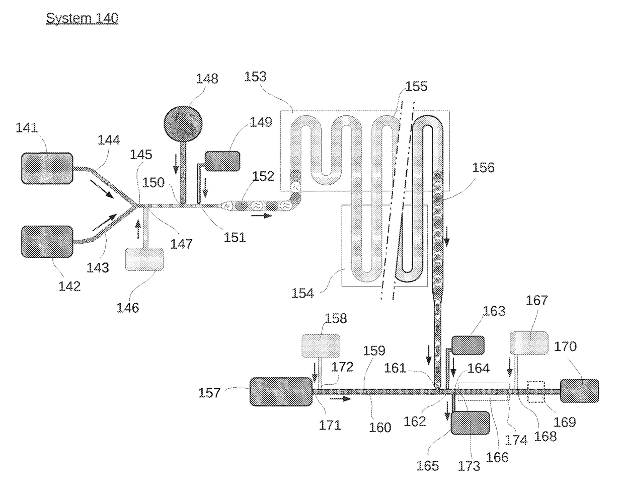
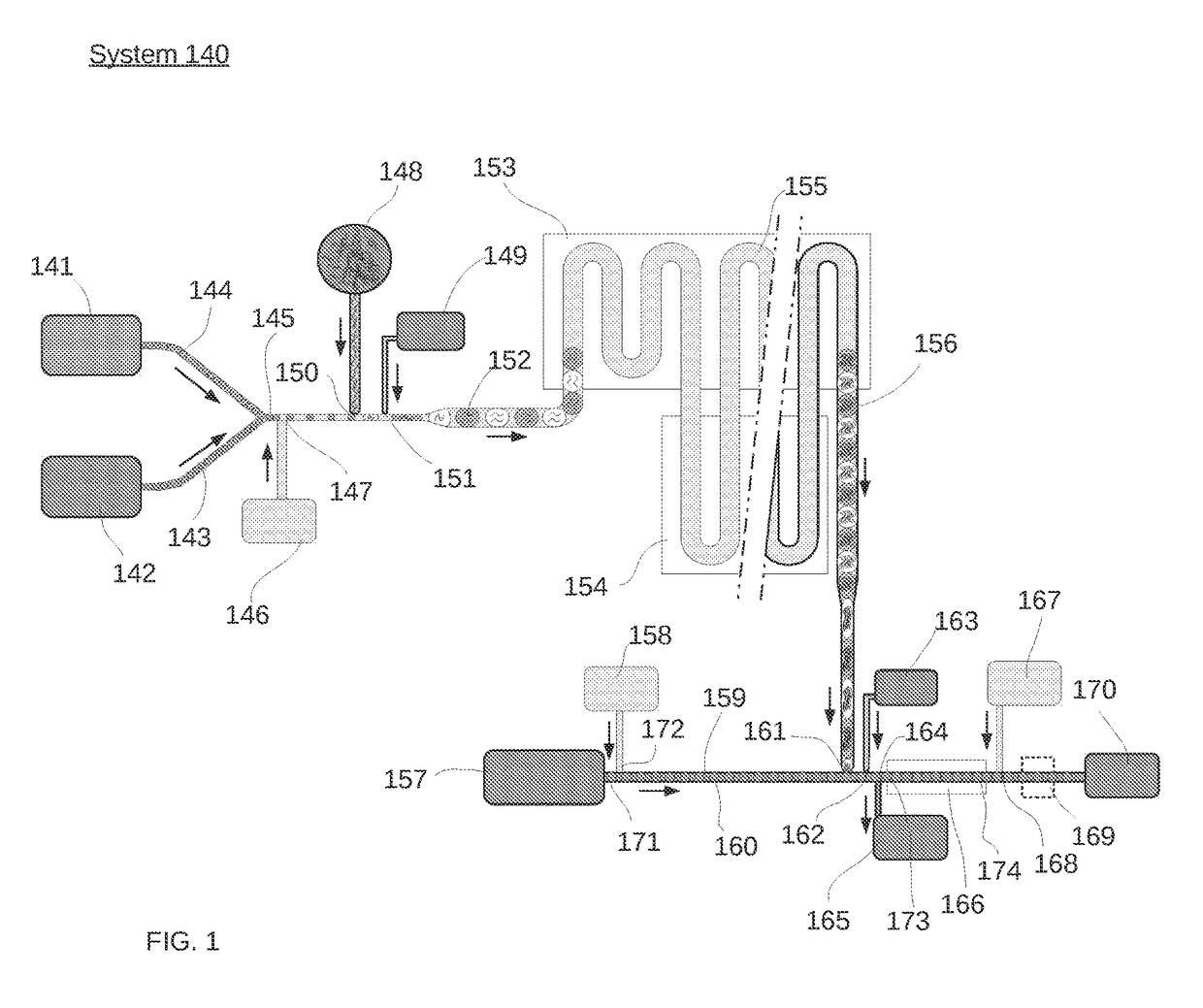
[0040]A variety of aspects for use in microfluidic systems are provided herein, including but not limited to methods of packing droplets and controlling emulsion flow within a microfluidic channel. The methods, devices and systems described herein can be used in isolation or adapted to any number of different microfluidic system configurations. One such system is depicted in FIG. 1. It should be recognized that the system of FIG. 1 is not intended to limit the invention. For example, aspects of the system of FIG. 1 can be used in separation from other aspects of the system while using the inventive configurations described herein.

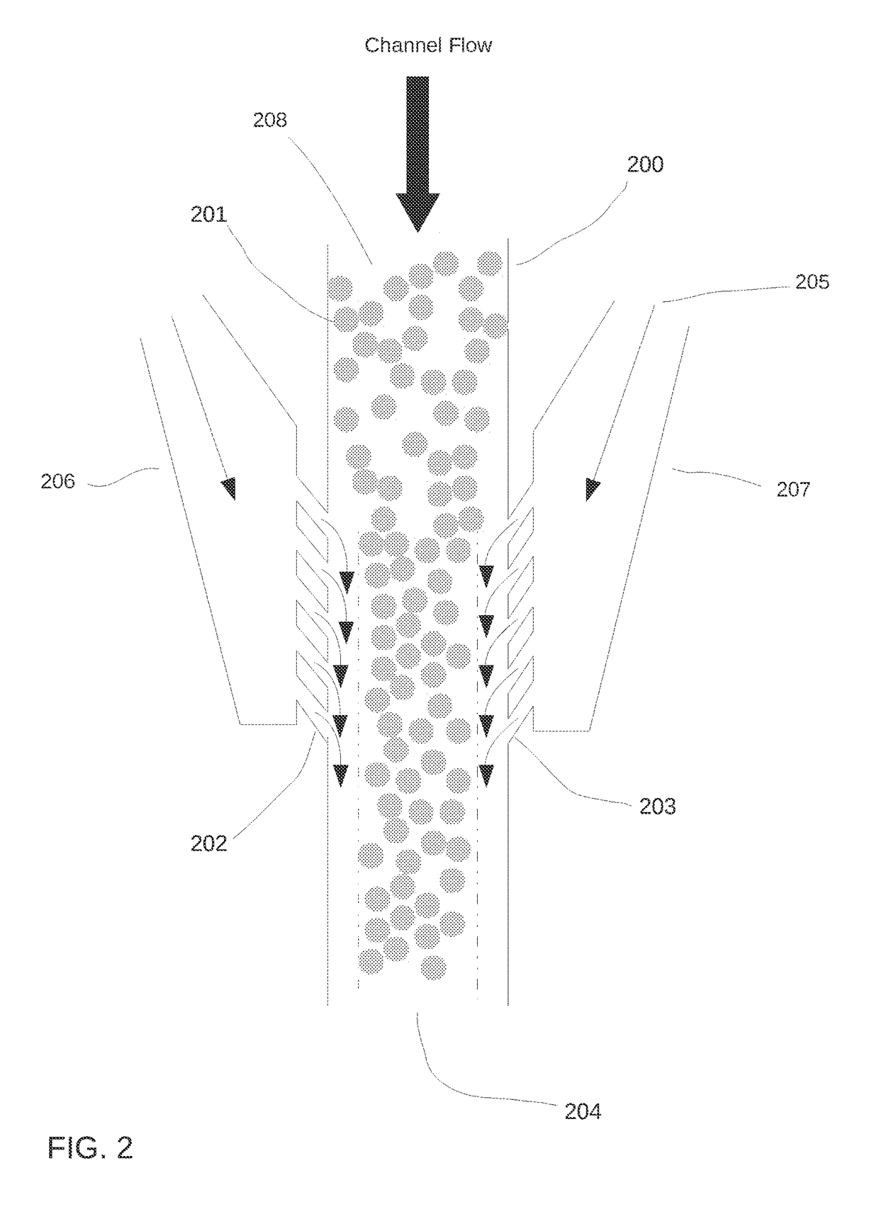
Controlling Droplets Flow in a Microfluidic Channel

[0041]In some aspects, a system and method is provided for confining drops within a portion of a microfluidic channel. More specifically, the present system provides for a system and method for controlling the introduction and removal of oil into a microfluidic channel in order to control where drops are al...


PUM


Abstract

Systems and methods for confining droplets within a microfluidic channel as well as systems and methods for packing droplets are provided. More specifically, a system and method are provided for controlling the introduction and removal of oil into a microfluidic channel in order to control where drops are allowed to flow within that channel.

Description

CROSS-REFERENCES TO RELATED APPLICATIONS[0001]The present application claims benefit of priority to U.S. Provisional Application No. 61 / 909,543, filed on Nov. 27, 2013 and U.S. Provisional Patent Application No. 61 / 934,190, filed on Jan. 31, 2014, each of which is incorporated by reference for all purposes.BACKGROUND OF THE INVENTION[0002]Microfluidic processes often employ the use of an emulsion, which contains drops of a dispersed liquid phase surrounded by an immiscible continuous liquid phase. Drops may be used as reaction vessels for chemical or biological reactions, as storage vessels, and / or as a method to isolate and compartmentalize molecules, such as chemical or biological elements. With proper chemistry such as surfactants on the surface of the emulsion, drops may be made “stable,” meaning they are substantially prevented form mixing and merging when in contact with each other. This stability allows one to create a population or library of drops composed of different chem...

Claims


Application Information

Patent Timeline
Patent Type & Authority Applications(United States)
IPC IPC(8): B01L3/00B01J19/00
CPCB01L3/502784B01J19/0093B01L3/502715B01J2219/00783B01J2219/00894B01L2300/0867B01J2219/00889B01L2200/0673B01L2300/0858B01L2400/0487B01J2219/00855B01J2219/00792B01J2219/00828B01J2219/00831B01J2219/00833B01J2219/00837B01J2219/0086B01J2219/00873B01J2219/00903B01J2219/00934B01L3/502776B01L7/525B01L2300/0816
Inventor HUNG, TONYKIANI, SEPEHRPOWERS, SCOTTESMAIL, ADNAN
Owner BIO RAD LAB INC
Why Eureka
Try Eureka