Multireflection cell, analyzer, exhaust gas analyzer, and light incident method

a multi-reflection cell and analyzer technology, applied in the direction of optical elements, instruments, optical radiation measurement, etc., can solve the problem that the absorbance of the measurement target gas cannot be accurately measured, and achieve the effect of increasing the light path length and keeping the measurement accuracy high

Inactive Publication Date: 2017-06-15
HORIBA LTD
View PDF11 Cites 13 Cited by
  • Summary
  • Abstract
  • Description
  • Claims
  • Application Information

AI Technical Summary

Benefits of technology

[0026]As described above, the multireflection cell of the present invention is configured such that the light incident into the multireflection mechanism is first reflected by the second objective mirror, and therefore reflection points on the field mirror can be concentrated in the central part and made sparse in the outer edge part. As a result, even when downsizing the multireflection cell, and increasing the number of times of reflection in the multireflection mechanism in order to increase a light path length, light emitted outward before reaching the prescribed number of times of reflection can be reduced to keep measurement accuracy high. Reflection light from an objective mirror can be preferably prevented from being emitted outward in the outer edge part of the field mirror before reaching the prescribed number of times of reflection.

Problems solved by technology

For this reason, the absorbance of the measurement target gas cannot be accurately measured.

Method used


Image

  • Multireflection cell, analyzer, exhaust gas analyzer, and light incident method
  • Multireflection cell, analyzer, exhaust gas analyzer, and light incident method
  • Multireflection cell, analyzer, exhaust gas analyzer, and light incident method

Examples


Embodiment Construction

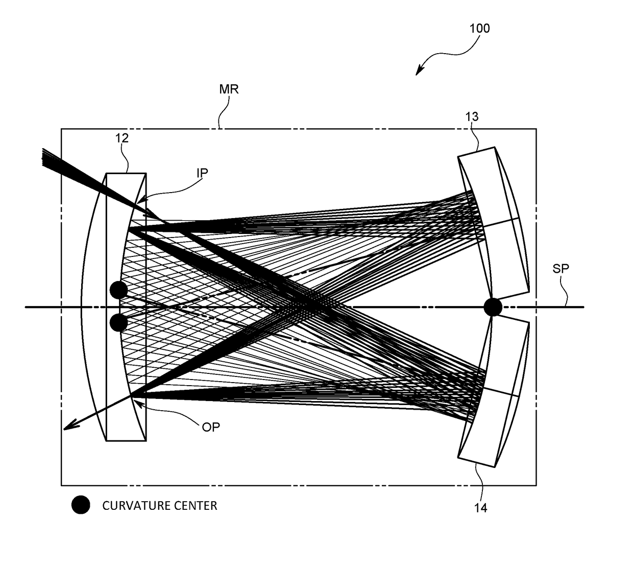
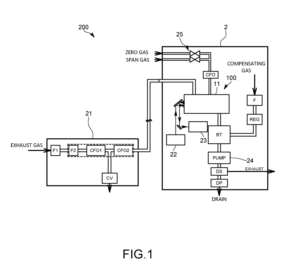
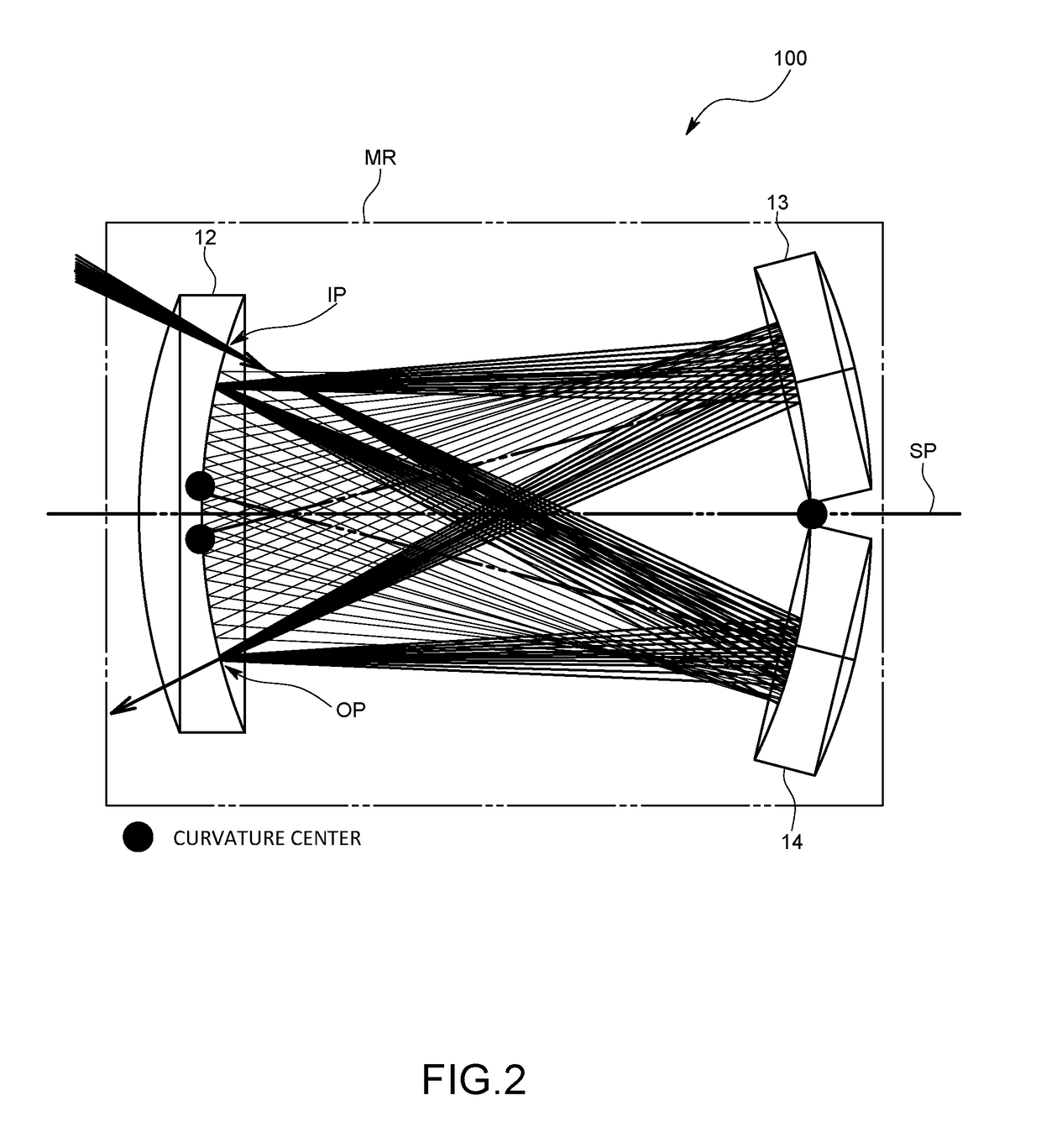
[0037]A multireflection cell 100 and analyzer 200 according to one embodiment of the present invention will be described with reference to FIG. 1.

[0038]The analyzer 200 of the present embodiment is used to measure the concentrations of multiple components contained in exhaust gas discharged from an internal combustion engine of an automobile as pieces of time series data. That is, the analyzer 200 of the present embodiment is configured as an exhaust gas analyzer.

[0039]As illustrated in FIG. 1, the analyzer 200 includes: a dilution mechanism 21 that is connected to the tail pipe of the automobile to sample part of the exhaust gas as well as diluting the sampled exhaust gas to a predetermined concentration with air; and an analysis mechanism 2 that is connected to the dilution mechanism 21 and measures the concentrations of the respective components in the exhaust gas from the diluted exhaust gas.

[0040]The analysis mechanism 2 is one adapted to measure the respective concentrations o...


PUM

PropertyMeasurementUnit
transmittanceaaaaaaaaaa
reflectionaaaaaaaaaa
path lengthaaaaaaaaaa

Abstract

In order to provide a multireflection cell making it possible to decrease the volume of a cell main body into which measurement target gas is introduced as well as reducing the amount of light that is lost without being reflected in a multireflection mechanism, the multireflection cell includes the multireflection mechanism adapted to multiply reflect incident light and then emit the multiply reflected light outward. In addition the multireflection mechanism includes a field mirror, a first objective mirror that faces to the field mirror and is provided on a light incident side in the multireflection mechanism, and a second objective mirror that faces to the field mirror and is provided on a light emitting side in the multireflection mechanism. Further, the light incident into the multireflection mechanism is configured to be first reflected by the second objective mirror.

Description

CROSS-REFERENCE TO RELATED APPLICATIONS[0001]This application claims priority to JP Application No. 2015-244552, filed Dec. 15, 2015, and JP Application No. 2016-074621, filed Apr. 1, 2016, the disclosures of which are incorporated in their entirety by reference herein.TECHNICAL FIELD[0002]The present invention relates to a multireflection cell adapted to multiply reflect incident light and then emit the multiply reflected light outward, and an analyzer using the multireflection cell.BACKGROUND ART[0003]Gas absorption analysis using, for example, FTIR (Fourier transform infrared) spectroscopy employs a White type multireflection cell having a multireflection mechanism that is configured to include multiple mirrors in order to decrease the required volume of measurement target gas as well as increasing the light path length of light passing through the measurement target gas (see Non-Patent Literature 1).[0004]A multireflection mechanism MR illustrated in FIG. 9 is arranged inside a ...

Claims


Application Information

Patent Timeline
Patent Type & Authority Applications(United States)
IPC IPC(8): G02B17/00G01N21/3504G01J1/04G02B17/06
CPCG02B17/004G01J1/0422G01N21/3504G02B17/0636G01N21/01G01N21/35G01N2021/3595G01N2021/0112G01N1/2252G01N21/031G01M15/108
Inventor AKAMATSU, TAKESHI
Owner HORIBA LTD
Why Eureka
Try Eureka