
Low-Rank and Sparse Matrix Decomposition Based on Schatten p=1/2 and L1/2 Regularizations for Separation of Background and Dynamic Components for Dynamic MRI

a dynamic mri and sparse matrix technology, applied in image enhancement, instruments, applications, etc., can solve the problem that the existing dynamic mri imaging techniques cannot reduce the scan time to a satisfactory level

Inactive Publication Date: 2017-06-15
MACAU UNIV OF SCI & TECH
View PDF0 Cites 12 Cited by
  • Summary
  • Abstract
  • Description
  • Claims
  • Application Information

AI Technical Summary

Benefits of technology

The patent describes a method for optimizing the pixel values in an image by minimizing a weighted sum of terms. The terms include a measure of the energy of the image, a measure of the energy of a low-rank component, and a measure of the energy of a sparse component. The method also includes optimizing a background component and a dynamic component of the image, which is the difference between the actual data and a reconstructed data sequence obtained by sub-sampling the image. The technical effect of this method is that it can improve the quality and reduce the size of images by compressing the image data while maintaining the important information contained in the image.

Problems solved by technology

However, in comparison with multi-detector computed tomography (CT), existing techniques for dynamic MRI imaging still cannot reduce the scan time to a satisfactory level.

Method used


Image

  • Low-Rank and Sparse Matrix Decomposition Based on Schatten p=1/2 and L1/2 Regularizations for Separation of Background and Dynamic Components for Dynamic MRI
  • Low-Rank and Sparse Matrix Decomposition Based on Schatten p=1/2 and L1/2 Regularizations for Separation of Background and Dynamic Components for Dynamic MRI
  • Low-Rank and Sparse Matrix Decomposition Based on Schatten p=1/2 and L1/2 Regularizations for Separation of Background and Dynamic Components for Dynamic MRI

Examples


Embodiment Construction

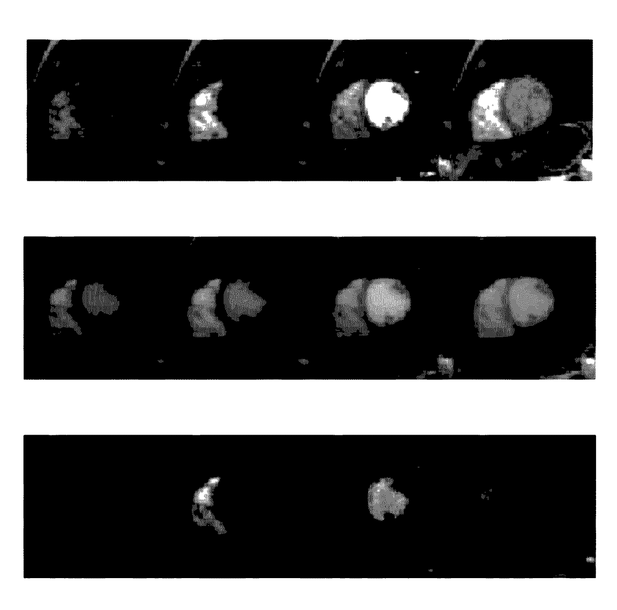
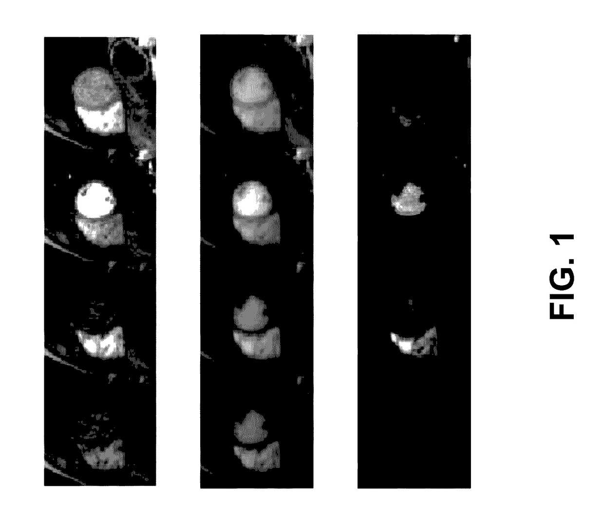
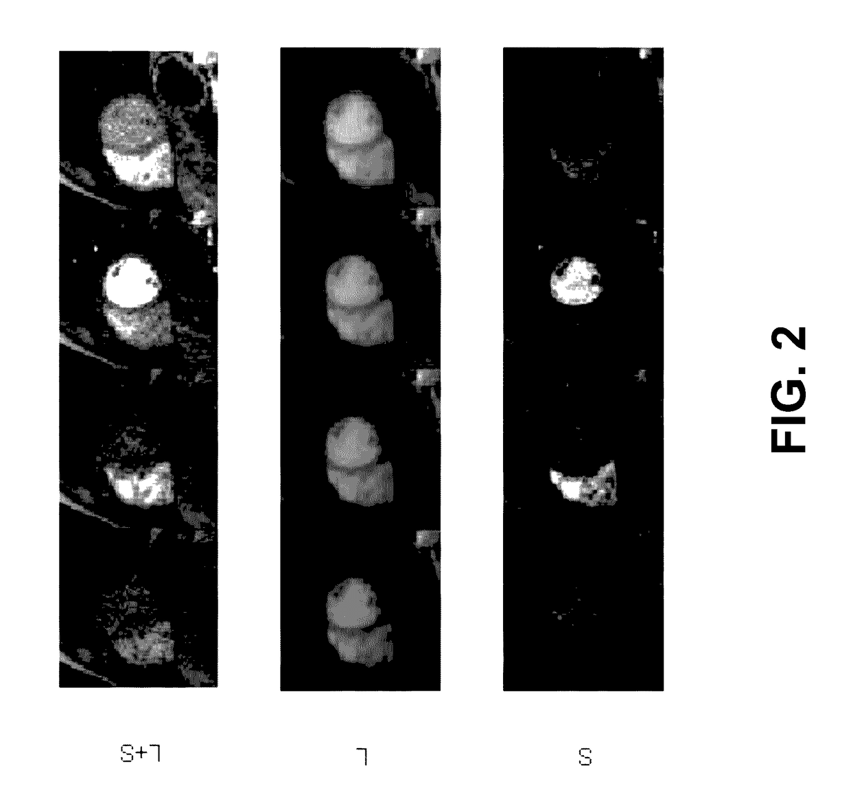
[0058]Traditionally, the L+S matrix decomposition has been performed by transforming the decomposition problem into a convex optimization problem of minimizing a nuclear-norm (viz., a sum of singular values) of a low-rank section of the matrix and an L1-norm (namely, a sum of absolute values) of a sparse section of the matrix subject to data consistency constraints [24]. Different from the traditional approach, herein in the present invention, an S1 / 2-norm and an L1 / 2-norm are used to replace the nuclear-norm and the L1-norm, respectively, for improving the performance of the L+S matrix decomposition.

[0059]The technique developed by the aforementioned improved approach was tested in experiments. To guarantee fairness and effectiveness in the experiments, several sets of data of dynamic MRI experiments from [16] were used, where joint multi-coil reconstruction was used for Cartesian and non-Cartesian k-space sampling. As will be shown, experimental results demonstrate the superiority...


PUM


Abstract

A method for determining a background component and a dynamic component of an image frame from an under-sampled data sequence obtained in a dynamic MRI application is provided. The two components are determined by optimizing a low-rank component and a sparse component of the image frame in a sense of minimizing a weighted sum of terms. The terms include a Schattenp=1 / 2 (S1 / 2-norm) of the low-rank component, an L1 / 2-norm of the sparse component additionally sparsified by a sparsifying transform, and an L2-norm of a difference between the sensed data sequence and a reconstructed data sequence. The reconstructed one is obtained by sub-sampling the image frame according to an encoding or acquiring operation. The background and dynamic components are the low-rank and sparse components, respectively. Experimental results demonstrate that the method outperforms an existing technique that minimizes a nuclear-norm of the low-rank component and an L1-norm of the sparse component.

Description

BACKGROUNDFIELD OF THE INVENTION[0001]The present invention relates to determining a background component and a dynamic component of an image frame from a sensed data sequence obtained in a dynamic magnetic resonance imaging (MRI) application, where the sensed data sequence is under-sampled with respect to the image frame.LIST OF REFERENCES[0002]There follows a list of references that are occasionally cited in the specification. Each of the disclosures of these references is incorporated by reference herein in its entirety.[0003][1] Lustig, M., Donoho, D., Pauly, J. M., “Sparse MRI: The application of compressed sensing for rapid MR imaging,”Magnetic Resonance in Medicine, 2007, 58(6): pp. 1182-1195.[0004][2] McGibney, G., et al., “Quantitative evaluation of several partial Fourier reconstruction algorithms used in MRI,”Magnetic Resonance in Medicine, 1993, 30(1): pp. 51-59.[0005][3] Barger, A. V., et al., “Time resolved contrast enhanced imaging with isotropic resolution and broad ...

Claims


Application Information

Patent Timeline
IPC IPC(8): G06T7/00A61B5/055G06K9/52H04N19/85G06T11/00G06K9/62
CPCG06T2207/10088G06T2207/20048G06T2207/20144G06T7/0012G06T11/008A61B5/055G06K9/52G06K9/6267G06T7/0079H04N19/85G06K9/6215A61B5/0044A61B5/0263G01R33/5608G01R33/5611G01R33/56308G01R33/56366H04N19/59
Inventor LIANG, YONGXIA, LIANG-YONGLIN, XU-XINLIU, XIAO-YINGCHAN, KUOK-FAN
Owner MACAU UNIV OF SCI & TECH
Learn More