Modular device for high-speed video vibration analysis

a module device and video vibration technology, applied in the field of vibration analysis, can solve the problems of high price, long preparation and installation time of accelerometers, and altering the vibration response of the structur

Active Publication Date: 2017-06-15
AIRBUS DEFENCE & SPACE
View PDF7 Cites 23 Cited by
  • Summary
  • Abstract
  • Description
  • Claims
  • Application Information

AI Technical Summary

Benefits of technology

[0012]The consideration, e.g., combination, of the estimation of the deformations and the determination of the depth information makes it possible to extract vibrational data from two orthogonal planes. In consequence, it is possible to sense any variation of the structure in any direction in space, wherein the camera arrangement, e.g., one or more high-speed cameras, is able to operate also in daylight conditions. The one or more high-speed cameras of the camera arrangement may be optical passive sensors, wherein no energy emission is required and a distance to the structure and / or the structures spatial extension can be handled by simply adjusting the optics set-up (i.e., focal length and field-of-view).

Problems solved by technology

Despite being very accurate and reliable, accelerometers need long preparation and installation time, demand highly qualified operators, load the structure under test with their own mass (thus altering the vibration response of the structure) and can only measure at discrete points.
The main drawbacks of LDVs are affordability (very high price), operability (LDVs' performance worsen with exposure to external daylight and fall off rapidly when the distance to the target increases), and versatility (they are active optical systems, characterized by high power consumption and typically “bulky”, i.e., they cannot be operated in limited space or too far from the surface to observe).

Method used


Image

  • Modular device for high-speed video vibration analysis
  • Modular device for high-speed video vibration analysis
  • Modular device for high-speed video vibration analysis

Examples


Embodiment Construction

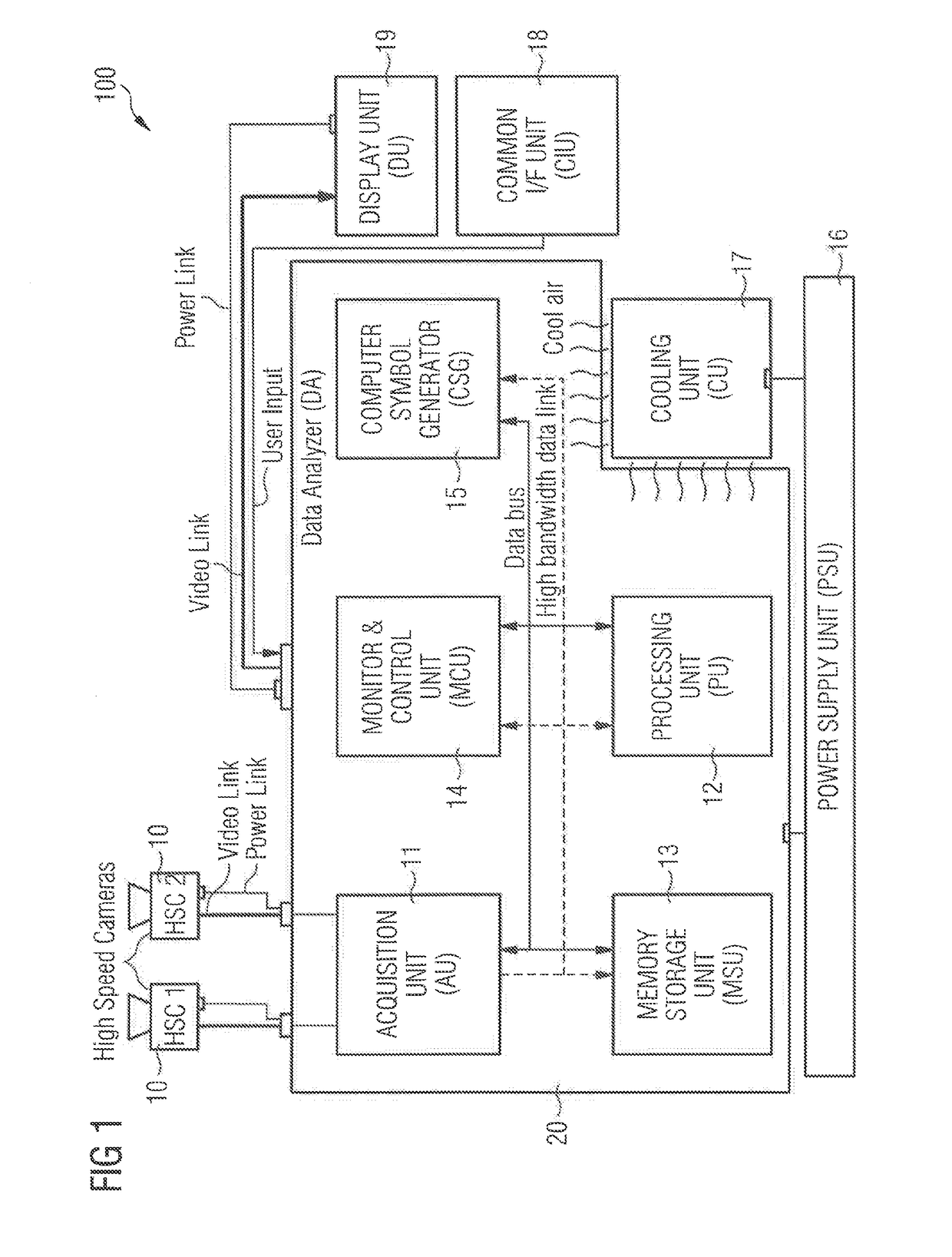
[0062]In the following description, for purposes of explanation and not limitation, specific details are set forth, such as specific algorithms, in order to provide a thorough understanding of the present disclosure. It will be apparent to one skilled in the art that the present disclosure may be practiced in other embodiments that depart from these specific details. For example, although the present disclosure is mainly described with reference to two high-speed cameras, any number of high-speed cameras is conceivable.

[0063]Those skilled in the art will further appreciate that functions explained herein below may be implemented using individual hardware circuitry, using software functioning in conjunction with a programmed microprocessor or a general purpose computer, using an Application Specific Integrated Circuit (ASIC) and / or using one or more Digital Signal Processors (DSPs). It will also be appreciated that when the present disclosure is described as a method, it may also be ...


PUM


Abstract

A technique for modular high-speed video vibration analysis of a structure. An embodiment of a device for high-speed video vibration analysis comprises a camera arrangement configured to generate at least two high-speed video streams of the structure and a data analyzer unit, connected to the camera arrangement. The data analyzer unit comprises a processing unit configured to extract vibrational data of at least a portion of the captured structure by considering estimated deformations of at least a portion of the captured structure along a first plane and determined depth information of at least a portion of the captured structure along a second plane different from the first plane or along an axis included in the second plane.

Description

CROSS-REFERENCES TO RELATED APPLICATIONS[0001]This application claims the benefit of the European patent application No. 15 199 331.8 filed on Dec. 10, 2015, the entire disclosures of which are incorporated herein by way of reference.BACKGROUND OF THE INVENTION[0002]The present disclosure generally relates to the field of vibration analysis. More specifically, the present disclosure relates to a technique for high-speed video vibration analysis of structures.[0003]Nowadays, vibration and structural health testing in the industry and, more specifically, ground and flight testing in the aeronautical industry, are based fundamentally on devices known as accelerometers. Despite being very accurate and reliable, accelerometers need long preparation and installation time, demand highly qualified operators, load the structure under test with their own mass (thus altering the vibration response of the structure) and can only measure at discrete points.[0004]More modern non-contact technolog...

Claims


Application Information

Patent Timeline
Patent Type & Authority Applications(United States)
IPC IPC(8): G06T7/292G06T17/00G01B11/16H04N13/02
CPCG06T7/292H04N13/0271H04N13/0246H04N13/0214G06T17/00H04N2013/0085G06T2207/10021G06T2207/10028G06T2207/10152H04N2013/0081G01B11/16G01H9/00G06T2207/20016G06T7/262G06T7/593H04N13/214H04N13/246H04N13/271G06T7/80G06T7/85G01M7/02G06T7/20
Inventor PEREZ ACAL, ANTONIOMARSIGLIA, GIANLUCANADALUTTI, DANIELE
Owner AIRBUS DEFENCE & SPACE
Why Eureka
Try Eureka