Impedance tuning circuit

Active Publication Date: 2017-06-15
NXP BV
View PDF6 Cites 12 Cited by
  • Summary
  • Abstract
  • Description
  • Claims
  • Application Information

AI Technical Summary

Benefits of technology

[0013]In another example, a method for tuning an antenna is disclosed. The method includes sensing current in an element using a current sensor, storing reference values for current and slop in a memory, and generating a control signal based on an output of the current sensor and reference values, and using the

Problems solved by technology

The environmental changes may cause non optimal signal transmission operation.
This mistuning causes power drop and large current variations in the power amplifier that provides the signal being transmitted via the an

Method used


Image

  • Impedance tuning circuit
  • Impedance tuning circuit
  • Impedance tuning circuit

Examples


Embodiment Construction

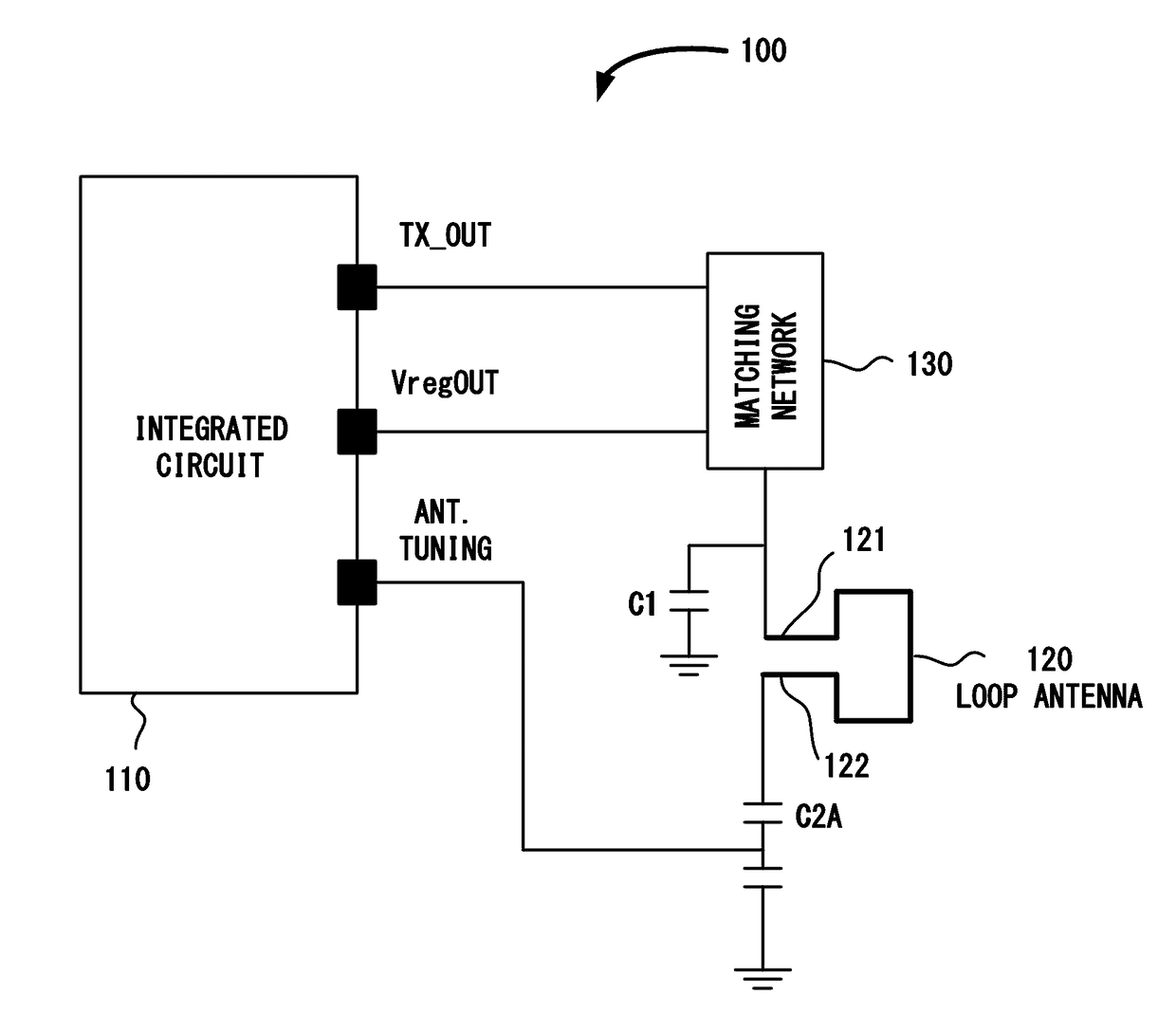
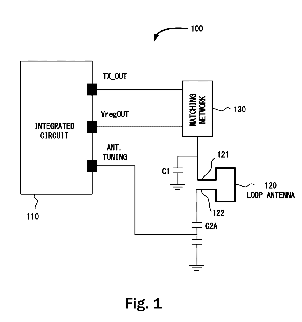
[0020]FIG. 1 illustrates a portion of a wireless system including automatic antenna tuning 100. The wireless system 100 includes an integrated circuit (IC) 110 that includes a circuit for automatically tuning an antenna 120 that is coupled to the IC 110. Typically but not necessarily, the antenna 120 is printed or embossed on a printed circuit board (PCB) and used in mobile devices, remote controls, keyless locking systems or similar applications in which a wireless communication is used. The wireless system 100 includes a matching network 130 that is typically a RLC or LC circuit or other combinations thereof, where R is resistance, L is inductance and C is capacitance.

[0021]Typically the matching network 130 is used to provide impedance matching. Typical loop antenna matching consists on capacitive termination for the antenna 120 in both terminals so that a choice of the capacitors coupled to the antenna 120 brings the inductance of the antenna 120 to resonate to provide an equiva...


PUM


Abstract

A circuit for tuning an impedance matching network is disclosed. The circuit includes a current sensor, a control circuit coupled to the current sensor and a reference current source and a tunable capacitor coupled to the control circuit. The control circuit is configured to generate a control signal based on an output of the current sensor, wherein the control signal is configured to vary a capacitance of the tunable capacitor.

Description

CROSS REFERENCE TO RELATED APPLICATION[0001]This application claims the benefit of U.S. Application No. 62 / 131,700, filed Mar. 11, 2015 which is incorporated herein by reference. This application is related to application Ser. No. 14 / 645,177 Docket No. 81672743US01 filed on Mar. 11, 2015.BACKGROUND[0002]Small Loop antennas in printed circuit boards (PCB) are commonly used in applications such wireless devices, for transmitting and receiving signals. The impedance of the antenna is inductive and sensitive to the environmental changes. The environmental changes may cause non optimal signal transmission operation. This mistuning causes power drop and large current variations in the power amplifier that provides the signal being transmitted via the antenna. The antennas are typically tuned at design or manufacturing stages and the devices containing these antennas are typically not configured to enable tuning of the antennas when the device is in use in the field.SUMMARY[0003]This Summa...

Claims


Application Information

Patent Timeline
IPC IPC(8): H01Q7/00H03H7/38H01G4/38
CPCH01Q7/005H03H7/38H01G4/38
Inventor VELANDIA TORRES, JAVIER MAURICIO
Owner NXP BV
Why Eureka
Try Eureka